Intel
®
Server Chassis P4304XXMFEN2/P4304XXMUXX Product Family System Integration and Service Guide
44
The table below shows the cables required for these storage drive options.
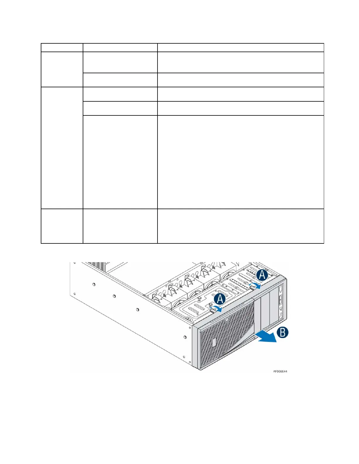
2.3.1 Removing the Front Bezel
Figure 50. Removing the Front Bezel
1. Remove the chassis side cover following instructions in Section 1.2.1. Before accessing the
storage device, remove the front bezel.
2. Push the two tabs on the front bezel outward until the tabs disengage from the chassis (see letter
A).
3. Lift the front bezel away from the chassis (see letter B).
4 drives
configuration)
Mini-SAS HD to 7-pin SATA (AXXCBL450HD7S), connect Mini-
SAS HD side to server board side and 7-pin SATA side to drives.
Cable shipped with chassis.
4x3.5 Hot-Swap
backplane/cage
Mini-SAS HD to Mini-SAS HD (AXXCBL380HDHD). Both server
board and backplane side are Mini-SAS HD type.
8 drives
Two 4x3.5 Hot-Swap
backplanes/cages
Mini-SAS HD to Mini-SAS HD (AXXCBL380HDHD). Both server
board and backplane side are Mini-SAS HD type.
8x2.5 Hot-Swap
backplane/cage
Mini-SAS HD to Mini-SAS HD (AXXCBL380HDHD). Both server
board and backplane side are Mini-SAS HD type.
backplane/cage
For S2600CW Server Board Family:
One PCIe* SSD cable for drive port 0-3 (shipped with
FUP8X25S3NVDK)
One Mini-SAS HD to Mini-SAS HD cable (AXXCBL380HDHD) for
drive port 4-7
For S2600ST Server Board Family:
OCuLink cable for 4 PCIe* SSDs
One Mini-SAS HD to Mini-SAS HD cable (AXXCBL380HDHD) for
drive ports 0-3 and/or 4-7
Note:
Refer to the Intel® Server Board S2600ST Product Family
Configuration Guide for details on cables used in this
16 drives
backplanes/cages
For S2600CW Server Board Family:
Mini-SAS HD to Mini-SAS HD cables (AXXCBL380HDHD)
For S2600ST Server Board Family:
Please refer to the S2600ST_P4000 Configuration Guide for