Intel
®
Server Chassis P4304XXMFEN2/P4304XXMUXX Product Family System Integration and Service Guide
56
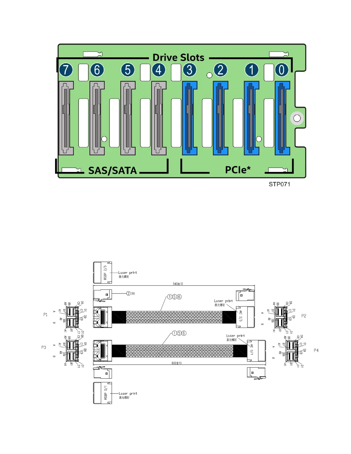
The figure below shows the PCIe* SSD and SAS/SATA Drive Slots on the backplane.
Figure 70. 8x2.5” PCIe* SSD (NVMe) Combo Backplane Front Side –S2600CW Board Family Only
The cables used to connect the NVMe add-in card to the 8x2.5” Combo backplane (PCIe* SSD Drive #0~3 Mini-
SAS HD cable connector) are shown in the illustration below. The left side of the cable connects to the
backplane; the right side of the cable connects to the PCIe* SSD add-in card.
Figure 71. NVMe Data Cables for 8x2.5” PCIe* SSD (NVMe) Combo Drive Bay Kit