Intel
®
Server Chassis P4304XXMFEN2/P4304XXMUXX Product Family System Integration and Service Guide
74
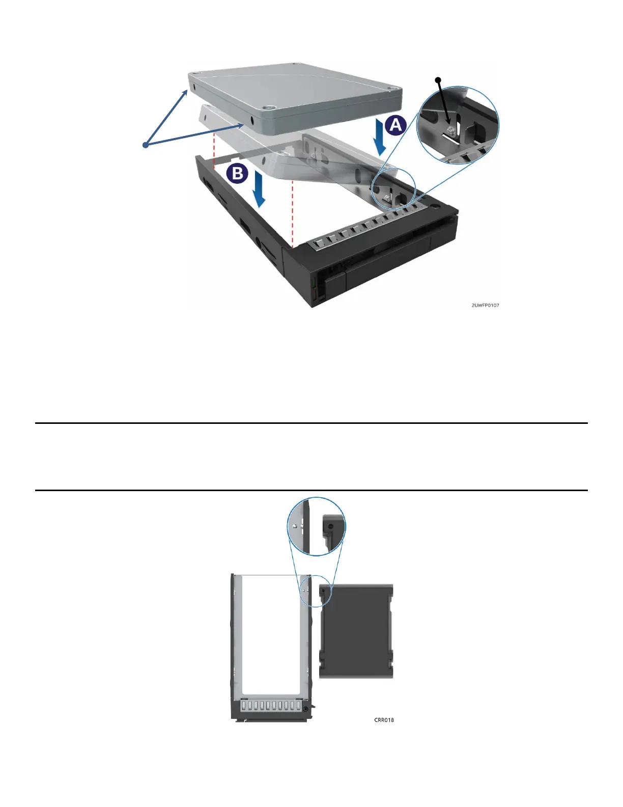
Figure 91. 2.5” Drive Carrier Assembly – Drive Installation to Carrier
2. With the rear drive connector positioned towards the back of the drive carrier, align and position
the mounting holes on one side of the drive over the mounting tabs located on the drive carrier
side rail (See letter “A”)
3. Lower the other side of the drive into the carrier (See letter “B”) and press down on the drive until
all mounting tabs are locked in place.
Note: The 2.5” drive blank and drive carrier each have an alignment feature (shown above) to ensure proper
assembly. When re-installing a drive blank in to the drive carrier, ensure the features are aligned prior to
installation. Failure to properly install a drive blank may result with the carrier assembly not fitting properly
in to the chassis drive bay.
Figure 92. 2.5” Drive Carrier Assembly – Alignment Features
Mounting Tab
(2 on each side)
Mounting Holes
(2 on each side)