Intel
®
Server Chassis P4304XXMFEN2/P4304XXMUXX Product Family System Integration and Service Guide
51
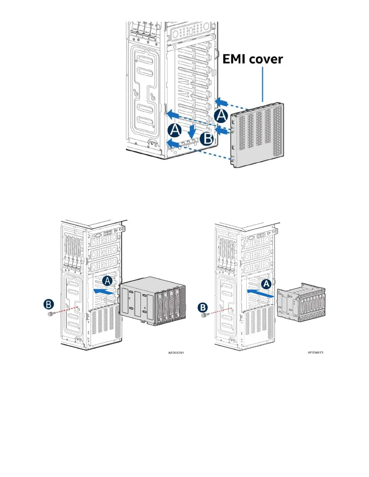
Figure 60. Installing the EMI Cover
5. Install the EMI cover from the Hot Swap Drive Bay Kit, by aligning the tabs on the EMI cover to the
chassis slots (see letter A) and slide it down (see letter B).
Figure 61. Installing a 4x3.5” or 8x2.5” Hot-Swap Drive Bay Kit
6. Slide the 4x3.5” or 8x2.5” Hot-Swap Drive Bay to the upper drive bay position (see letter A).
7. Secure the drive bay with the thumb screw from the Hot Swap Drive Bay Kit (see letter B).