Intel
®
Server Chassis P4304XXMFEN2/P4304XXMUXX Product Family System Integration and Service Guide
75
2.3.9.4 3.5” HDD/SSD Drive Carrier Assembly
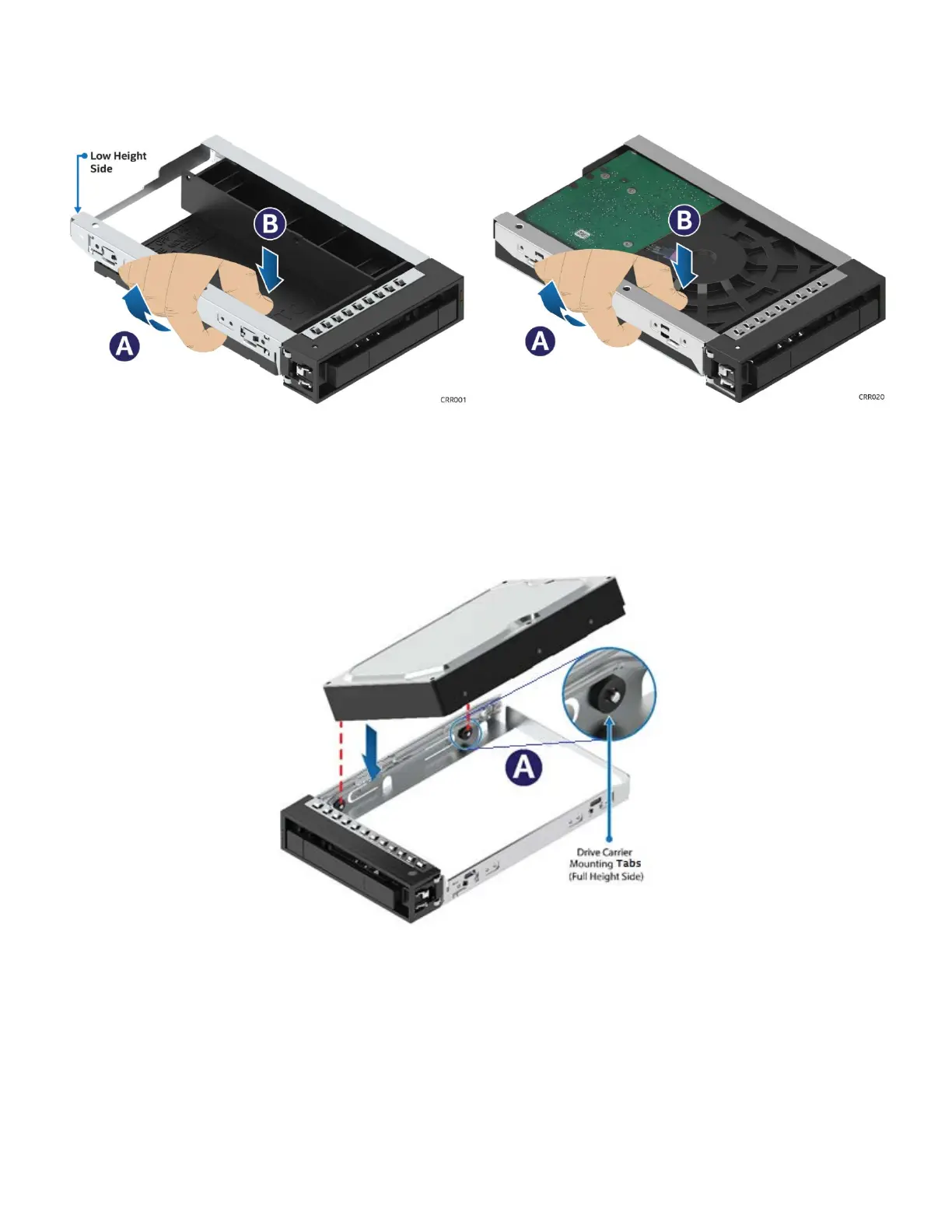
Figure 93. 3.5" Drive Carrier Assembly - Drive / Drive Blank Removal
1. Remove the drive or drive blank from the carrier by holding the carrier assembly top side down in your
right hand. Using your left hand, gently rotate the bottom edge of the left rail upwards (see Letter “A”)
while at the same time pushing the drive or drive blank down away from the carrier (see Letter “B”).
Figure 94. 3.5” Drive Carrier Assembly – Drive Installation to Carrier
2. With the rear drive connector positioned towards the back of the drive carrier, align and position the
mounting holes on the left side of the drive over the mounting tabs located on the drive carrier side rail
(See letter “A”)
3. Lower the other side of the drive into the carrier and press down until all mounting tabs lock in place.
2.3.9.5 2.5” SSD into a 3.5” Drive Carrier Assembly
The 3.5” drive blank can be used as a 2.5” SSD bracket.