Intel
®
Server Chassis P4304XXMFEN2/P4304XXMUXX Product Family System Integration and Service Guide
60
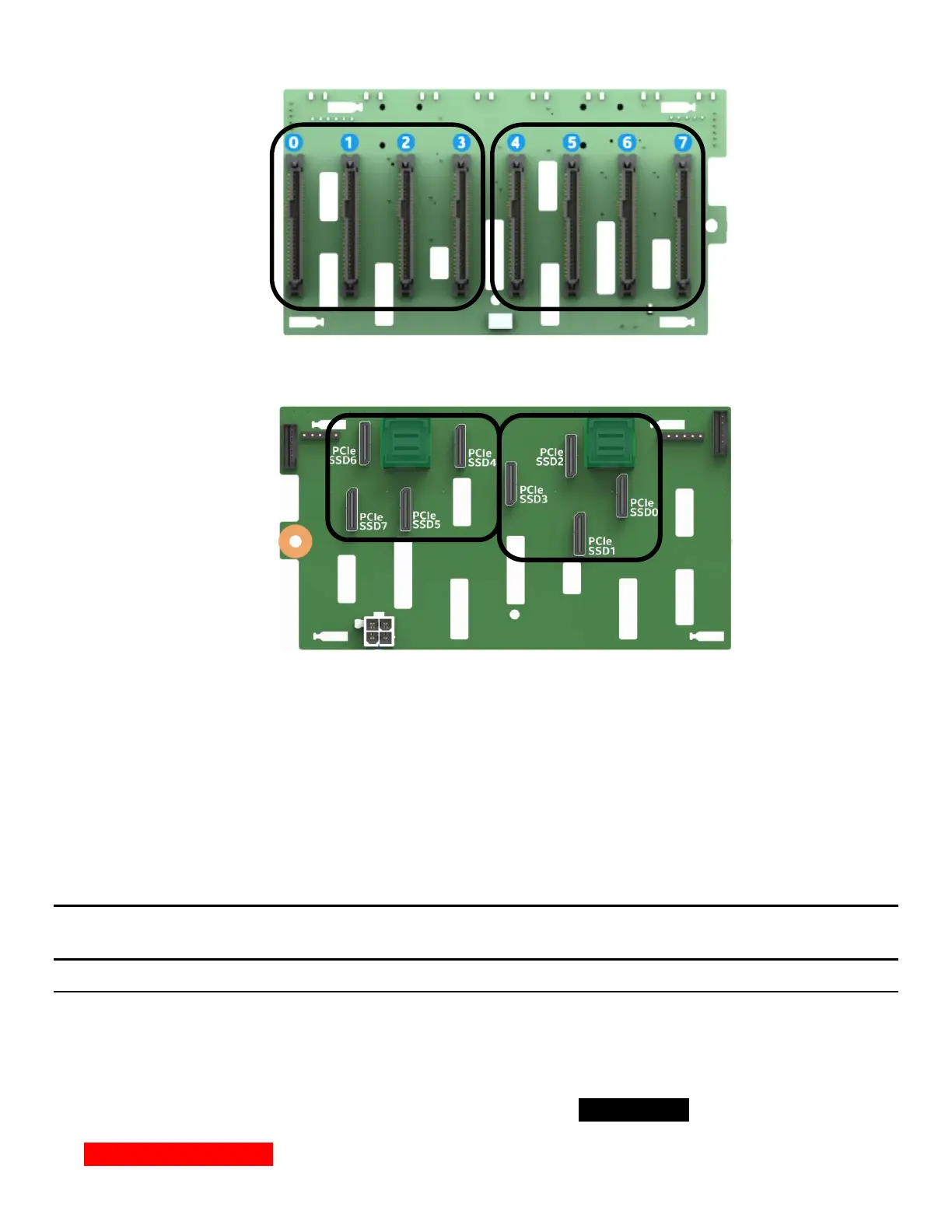
Figure 75. Backplane Cabling from Two PCIe Sources
When cabling the backplane from two different PCIe sources, no other drive set combinations beyond those
defined above are supported.
Drive population rules will differ depending on the source of the PCIe interface to the backplane. In addition,
specific drive population limits exist when populating a backplane with both NVMe and SAS/SATA drive
types.
The following sections define the drive population rules for an installed 2.5” x 8 combo backplane when
cabled to a specific PCIe source.
NOTE: When connecting the backplane to two different PCIe sources, the defined population rules for each
PCIe source are applied to the drive set connected to it
Onboard PCIe OCuLink Connectors and / or Intel Tri-mode RAID module to 8 x 2.5” Combo Backplane
The following information is applicable when PCIe signals to the 8x2.5” combo backplane are cabled from
the PCIe OCuLink connectors located on the server board and/or an optionally installed Intel® Tri-mode
RAID Module.
• OCuLink connectors on the server board are considered a single PCIe source to the backplane, and
therefore can only be connected in defined drive sets: PCIe_SSD (0-3) or (4-7)
• NVMe drive management sideband signals on the backplane are routed between drive connector pairs:
(0,1) (2,3) (4,5) and (6,7)
PCIe Source #1
PCIe Source #2
PCIe Source #1
PCIe Source #2
Front Drive Connectors
Back OCuLink Cable Connectors