EasyManuals Logo
Home>Intel>Chassis>P4304XXMFEN2

Intel P4304XXMFEN2 User Manual

Intel P4304XXMFEN2
194 pages
To Next Page IconTo Next Page
To Previous Page IconTo Previous Page
Page #83 background imageLoading...
Page #83 background image
Intel
®
Server Chassis P4304XXMFEN2/P4304XXMUXX Product Family System Integration and Service Guide
65
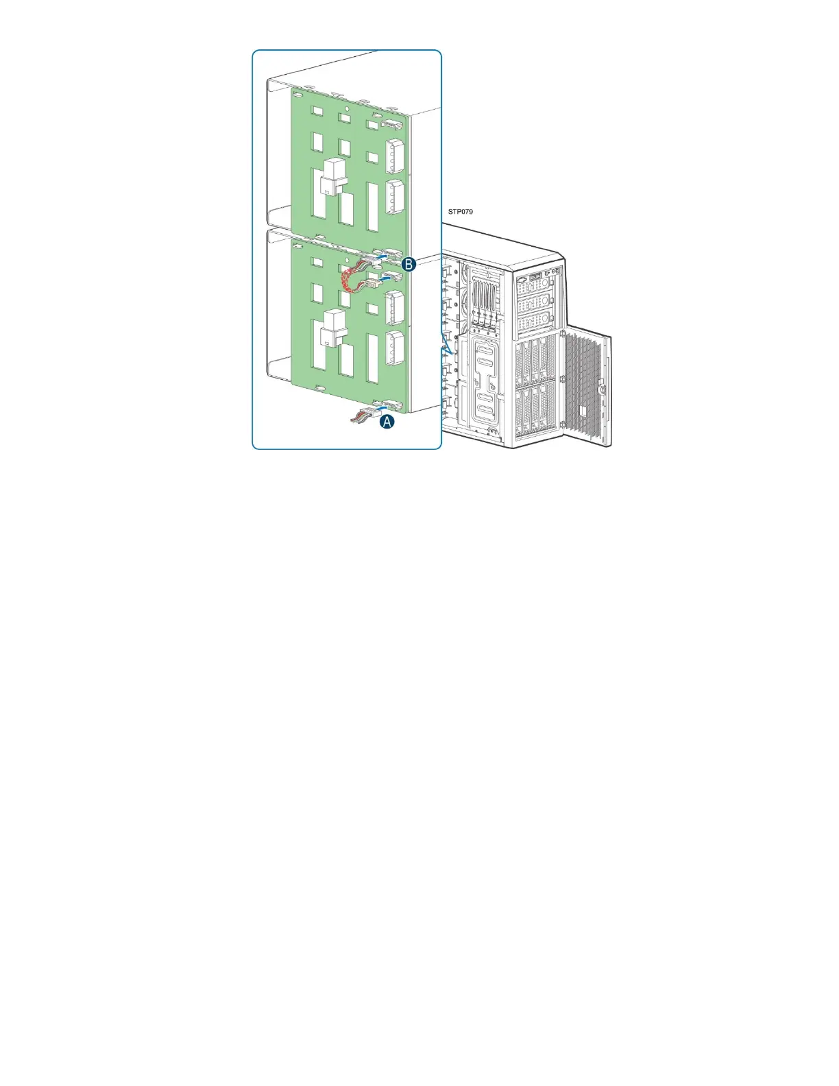
Figure 77. Interconnection Diagram for Two 4x3.5” Hot-Swap Drive Bay Kits
6. Connect one end of the C cable to the HSBP_I²C header on the server board and the other end
to the I²C_IN header on the backplane. See Appendix B for routing the I²C and Mini-SAS HD
cables. (See letter A).
7. Connect one end of the cascading I²C cable to the I²C_OUT header on the backplane in the
lower/left position and the other end to the I²C_IN header on the backplane in the upper/right
position (see letter B).

Table of Contents

Questions and Answers:

Question and Answer IconNeed help?

Do you have a question about the Intel P4304XXMFEN2 and is the answer not in the manual?

Intel P4304XXMFEN2 Specifications

General IconGeneral
BrandIntel
ModelP4304XXMFEN2
CategoryChassis
LanguageEnglish

Related product manuals