Intel
®
Server Chassis P4304XXMFEN2/P4304XXMUXX Product Family System Integration and Service Guide
55
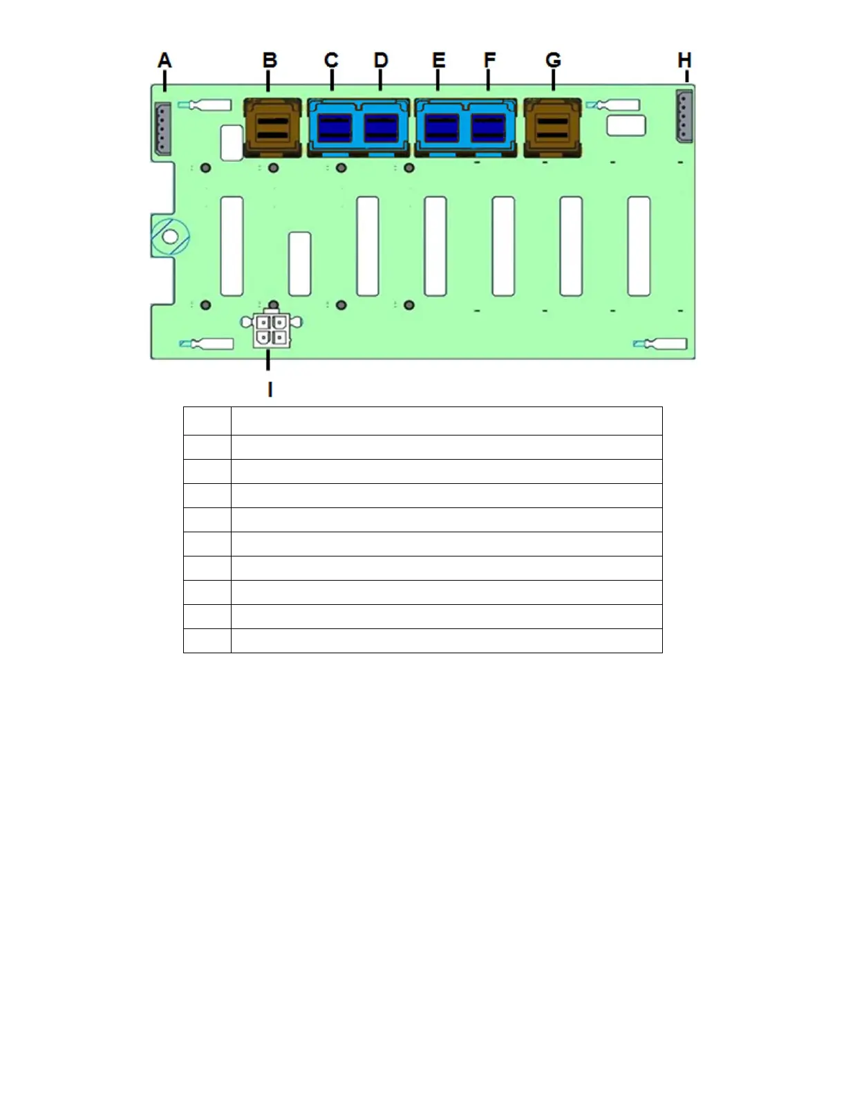
Label Description
SMBus-Out (I²C OUT) cable connector for multi-backplane support
SAS/SATA Ports 4-7 Mini-SAS HD cable connector
PCIe* SSD Drive #3 Mini-SAS HD cable connector
PCIe* SSD Drive #2 Mini-SAS HD cable connector
PCIe* SSD Drive #1 Mini-SAS HD cable connector
PCIe* SSD Drive #0 Mini-SAS HD cable connector
SAS/SATA Ports 0-3 Mini-SAS HD cable connector
SMBus-In (I²C IN) cable connector – From Server board or other backplane
Figure 69. 8x2.5” PCIe* SSD (NVMe) Combo Backplane Features – Only for S2600CW Board Family
4. Connect the I²C cable from the server board HSBP_I²C header to the backplane I²C_IN (SMBus-in)
header. See Figure 64 for header location on the server board.
5. If SAS/SATA drives will be used in Drive Slot 0-3, connect the “Mini-SAS HD to Mini-SAS HD”
cable to the backplane connector G. If SAS/SATA drives will be used in Drive Slot 4-7, connect the
“Mini-SAS HD to Mini-SAS HD” cable to the backplane connector B. The other end of the Mini-SAS
HD connector can be connected to the motherboard connector sSATA_0-3, SATA_0-3, SAS_0-3,
or SAS_4-7. See Figure 64 for the connector location on the server board.