Intel
®
Server Chassis P4304XXMFEN2/P4304XXMUXX Product Family System Integration and Service Guide
4
1.2 Server Building Block Installation
As received, the Intel Server Chassis will include several components within a boxed accessory kit or placed
within the chassis.
1.2.1 Chassis Side Cover Removal / Installation
1.2.1.1 Chassis Side Cover Removal
Operate the server with the chassis side cover in place to ensure proper cooling. Remove the side cover to add
or replace components inside of the chassis. Before removing the side cover, power down the chassis and
unplug all peripheral devices and the AC power cable(s).
Note: A non-skid surface or a stop behind the server chassis may be needed to prevent the server chassis
from sliding on a work surface.
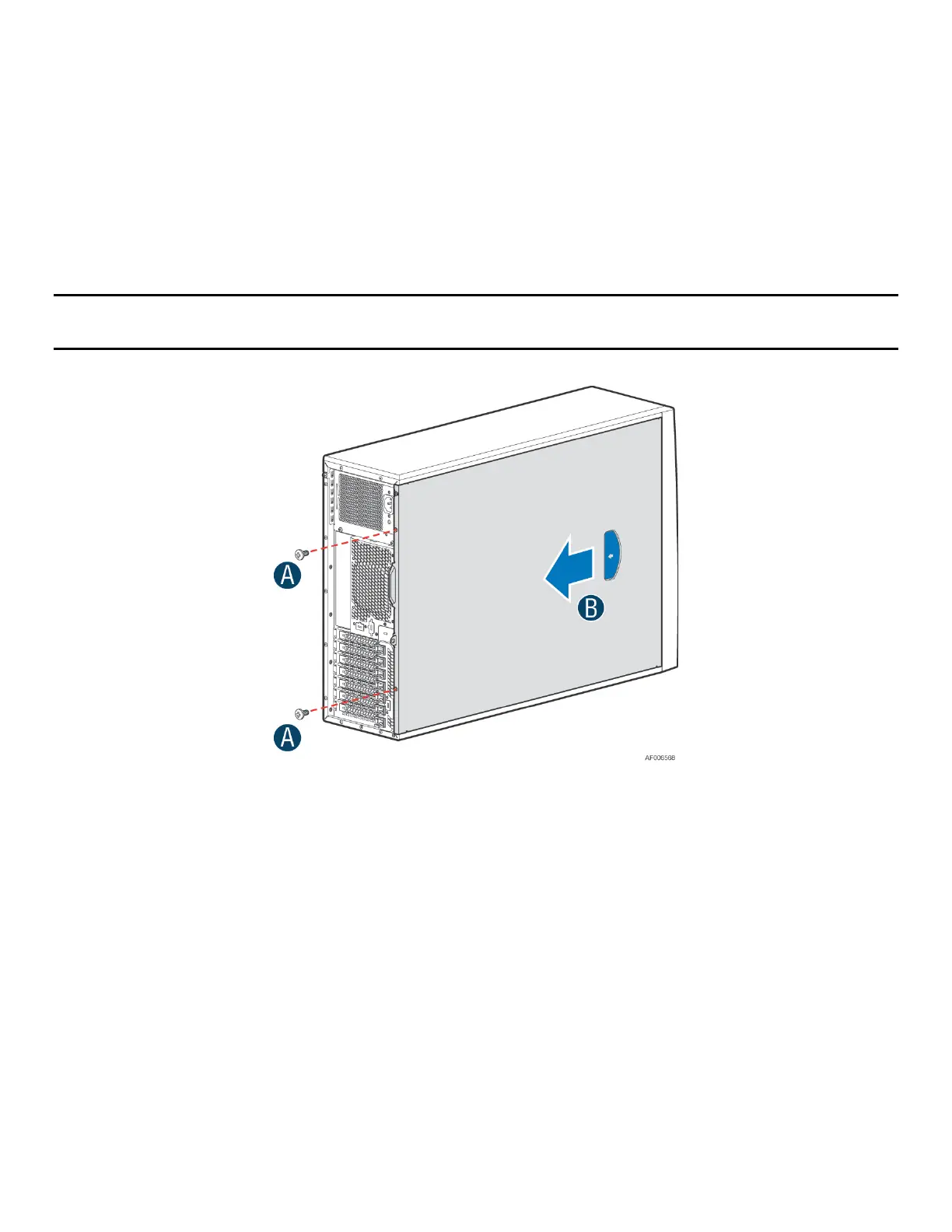
Figure 3. Removing the Chassis Side Cover
1. Loosen the two screws located on the back edge of the chassis side cover (see letter A).
2. Slide the cover back and lift it away (see letter B).
The accessory kit and or system packaging will include the following components:
• Bag of screws for mounting the server board
• Set of standoff screws for mounting the server board
• Dual power Connector Cable
• Mini-SAS HD to 4 ports SATA 7 pins cable
• Bag with a set of Chassis plastic Feet
• Bumper pad for server board
The following components will be found inside the chassis. Each should be removed:
• Plastic air duct