Intel
®
Server Chassis P4304XXMFEN2/P4304XXMUXX Product Family System Integration and Service Guide
54
2.3.5 Upgrading the Fixed Drive Storage to 8x2.5” PCIe* SSD (NVMe) Combo Drive Bay
Storage
2.3.5.1 For S2600CW Server Board Family
The installation of the 8x2.5” SAS/PCIe* SSD (NVMe) combo drive bay involves several components:
• NVMe add-in card
• 8x2.5” SAS/PCIe* SSD (NVMe) Combo Drive Bay Kit (FUP8X25S3NVDK)
• NVMe cables
• Mini-SAS HD to Mini-SAS HD cables (optional)
• I²C cable
1. Refer to section 2.3.4 for installing the Hot-swap Drive Bay kit.
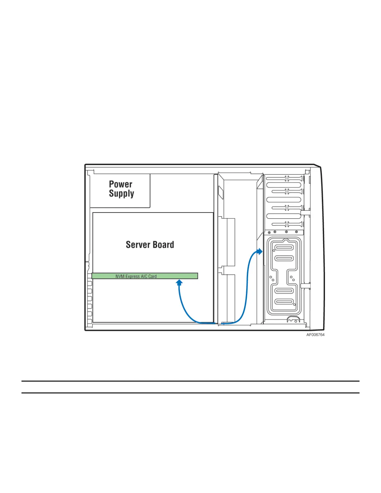
Figure 68. Installing an NVMe Add-in Card – S2600CW Board Family
2. Install the NVMe add-in card to any PCIe* x16 slot on the server board.
Note: The PCIe* slot 5 will be PCIe* x8 bandwidth on S2600CW2S and S2600CWTS.
3. Connect the NVMe cables to the NVMe add-in card and the 8x2.5” SAS/PCIe* SSD (NVMe) Combo
backplane. The cables are included in the accessory kit
.