237
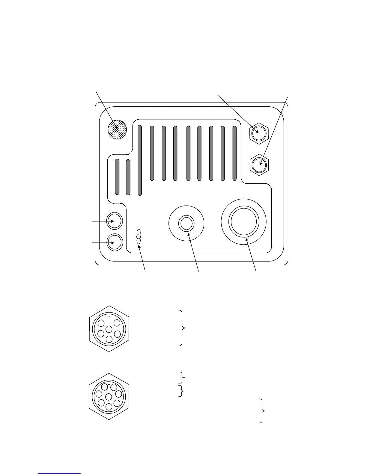
9.3.4 Display unit rear panel
1
2
3
4
5
6
GPS connector (J3)
2
3
4
5
6
8
1
7
External connector (J4)
F1
F1F1
F1
F2
F2F2
F2
E
EE
E
EXT2
EXT2EXT2
EXT2
EXT1
EXT1EXT1
EXT1
GPS
GPSGPS
GPS
POWER
POWERPOWER
POWER
SC
SCSC
SC
UNIT
UNITUNIT
UNIT
Ground terminal
Power connector (J1)
Cable assembly connector (J2)
Fuse (F2)
Fuse (F1)
GPS connector (J3)
External
connector (J4)
Rubber stopper
(for connecting the optional ex-
ternal connector (J5))
①
+12V
②
GND
③
NAVCOM
④ NAVRX
⑤ NAVTX
① DATA+
②
DATA-
③
CMPS+
④ CMPS-
⑤ SVD (Image signal)
⑥
SHS (Horizontal synchronization signal)
⑦ SVS (Vertical synchronization signal)
⑧
GND
To GPS or LORAN
To cursor data input device
To electromagnetic compass/ GPS compass
To sub-monitor
 Loading...


