243
9.5.2 Power cable (CFQ-6776)
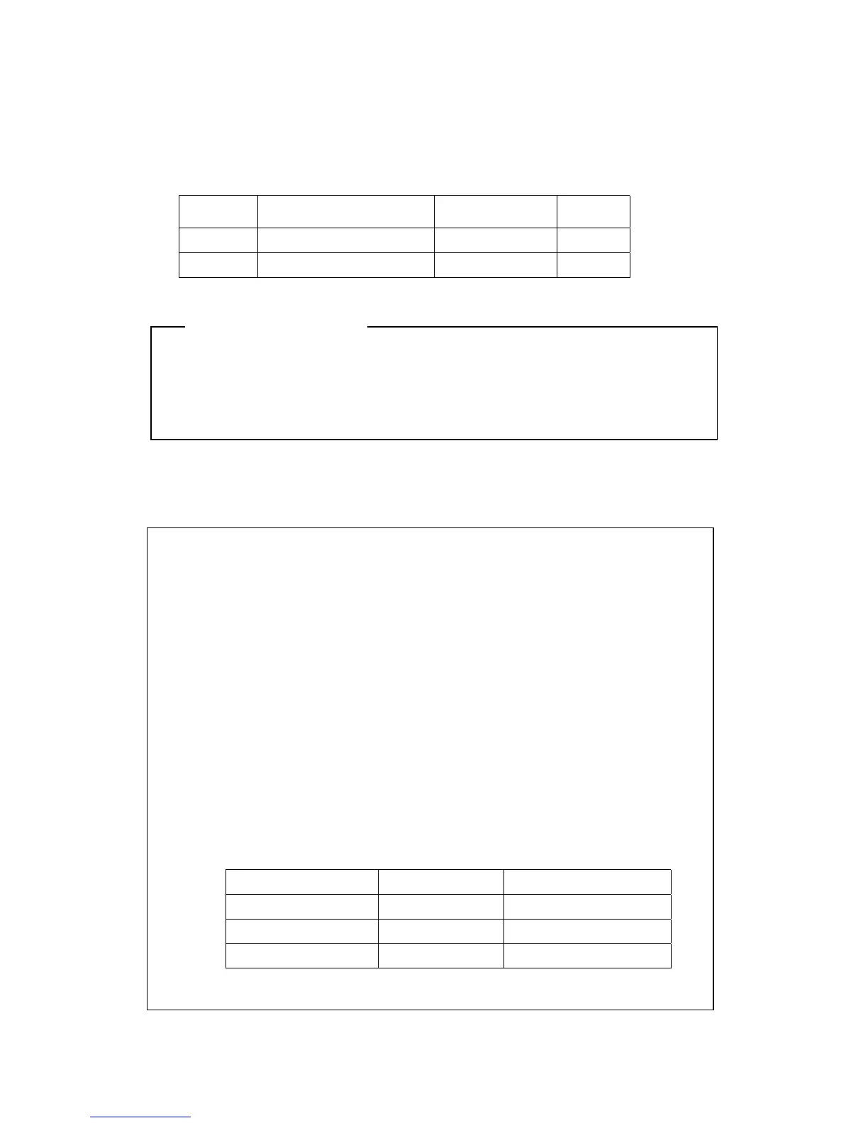
The radar unit is provided with a 2 m power cable with connectors
Color
Number of Conductors
/Diameter
Cross Section
(mm
2
)
Polarity
White 50/0.18 1.25
+
Black 50/0.18 1.25
-
Ensure that the output of the inboard power supply and rectifier unit and connection to
the power cable is correct.
Erroneous connection or voltage may cause breakdown.
9.5.3 Selecting a long cable
The effective voltage of the input to the radar is the voltage at the inboard power
supply minus the voltage drop caused by the power cable. Too thin or long a
power cable incurs a large voltage drop and may not be able to supply adequate
power to the radar. In is recommended that the following guidelines be observed
when selecting the power cable for your radar:
(a) Consider the possible voltage regulation of the inboard power supply (Vs).
(b) Use the following equation to calculate the voltage drop:
V=2LRKI
L:represents the cable length.
R:represents the direct-current resistance (<Ω>/m) at 20<℃>
K:represents the conductor resistance temperature coefficient (= 1.22)
I :Maximum peak current (A)
(c) The table below lists the direct-current resistance (R) and permissible current
(Imax) of several cables.
Cable Type
R (20℃) Imax (45℃, continuous)
CVVS2×1.25 16.7 Ω.km
13A
CVVS2×2.0 9.42 Ω/km
19A
CVVS2×3.5 5.30 Ω/km
26A
The cable to be used must possess a sufficient permissible current (Imax) characteristic.
Attention
 Loading...


