238
※ The following should be used as the plug side connector for connecting to J3 and J4
Connector Type JRC Code
For J3 LTWD-06BFFA-L180 5JCDX00014
For J4 LTWD-08BFFA-L180 5JCDX00015
9.3.5 Connection of the external buzzer
CAUTION
Only qualified service personnel should perform external buzzer cabling work.
Erroneous connection may cause breakdown or defective operation.
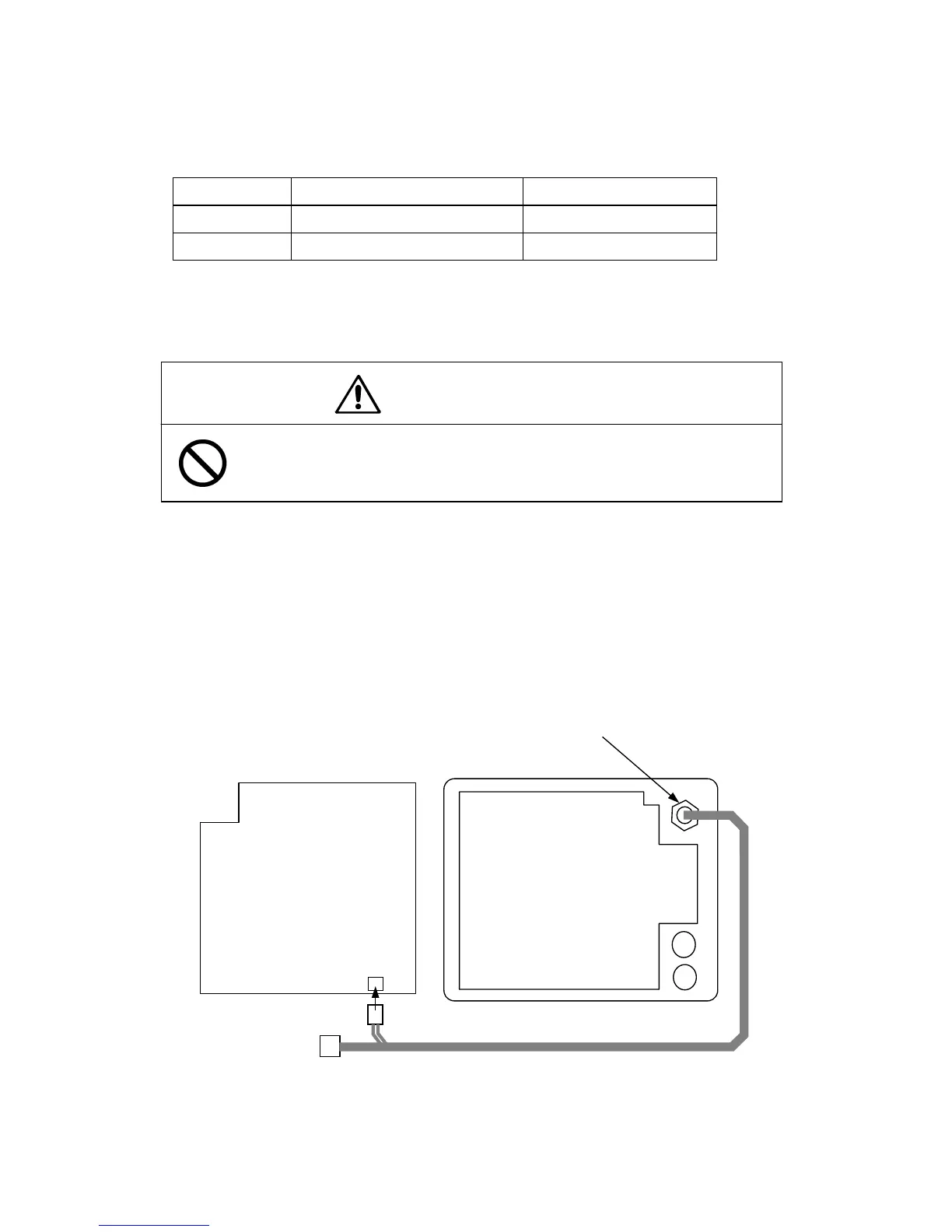
The 5 pin connector side of the cable equipped with connector (7ZCRD0749) should be
attached to EXT2 on the rear panel of display unit after removing the rubber stopper. The
2 pin connector side should be connected to J5 of the display unit main control circuit
(CMC-1156). The 3 pin connector need not be.
Use the 5 pin connector (Type: LTWD-05BFFA-L180, JRC code: 5JCDX00015) for the plug
side connector connected to EXT2.
J5 (2 pin)
Main control circuit
(CMC-1156)
Power supply circuit
(CBD-1596)
F1
F2
External connector J5 (5 pin)
 Loading...


