240
9.3.6 Connecting an electromagnetic compass
Ensure that the output of the inboard power supply and rectifier unit and connection to
the power cable is correct.
Erroneous connection or voltage may cause breakdown.
It is possible to input information on bearing to the radar display unit if you use the elec-
tromagnetic compass with a NMEA0183 output terminal.
(It is impossible to connect if you use the electromagnetic compass without a NMEA0183
output terminal.)
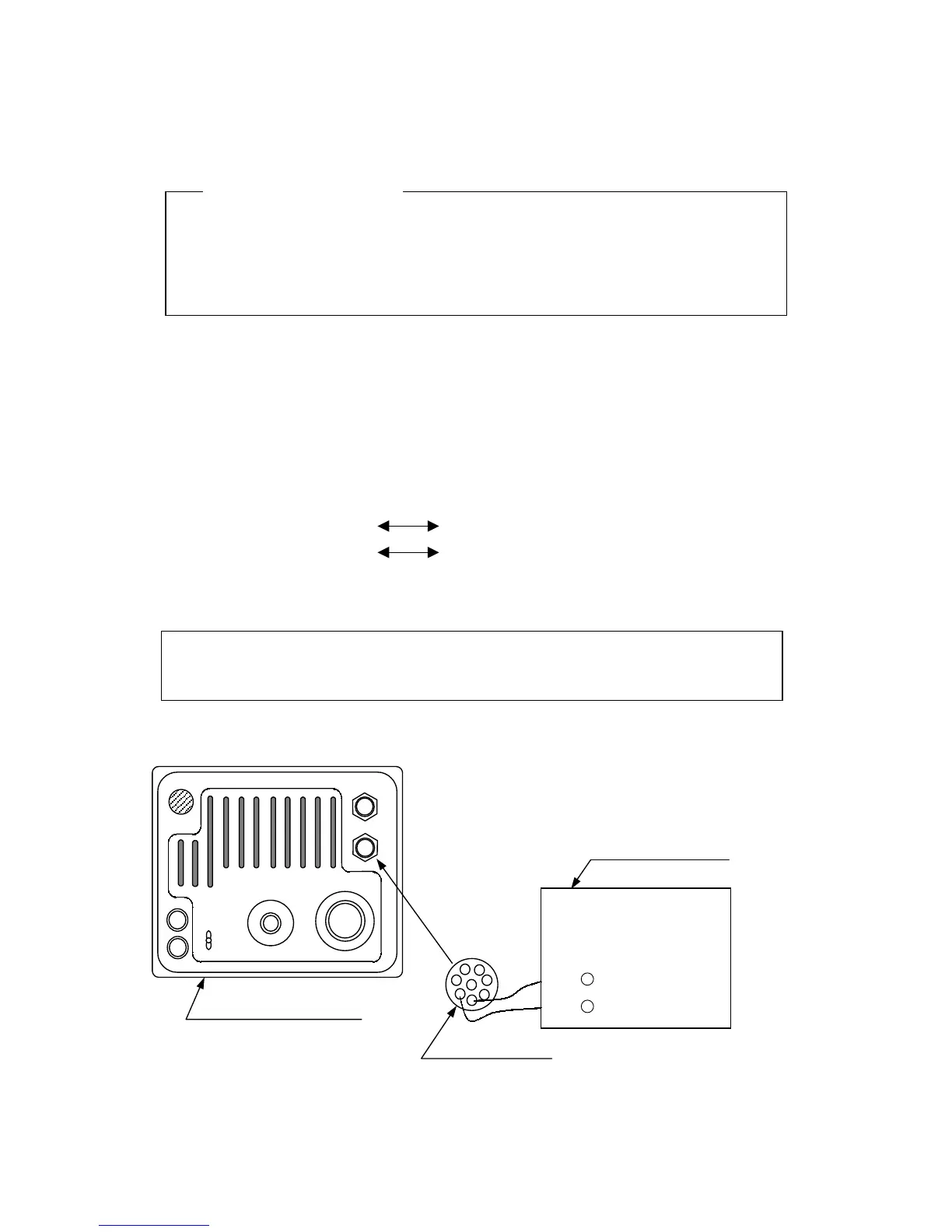
(1) Solder the data cable of electromagnetic compass (with NMEA0183 output) to the 8 pin
connector. The polarity is as shown below and care should be taken in making this
connection.
8 pin connector (pin 3) Electromagnetic compass data (+)
8 pin connector (pin 4) Electromagnetic compass data (-)
Type of LTWD-08BFFA-L180 (JRC code: 5JCDX00015) should be used as the 8 pin
connector.
Unless the connection between the 8 pin connector and data cable is correct,
correct data will not be obtained.
(2) Connect the 8 pin connector to J4 (EXT1) on the rear panel of the display unit.
This completes the cabling of the electromagnetic compass.
Attention
Electromagnetic compass
F1
F2
 Loading...


