2-14 Keysight B1505A Configuration and Connection Guide
N1259A Connection Guide
Output Connection
To Use Module Selector
The module selector is used to switch the measurement resource connected to a terminal of
DUT. The measurement resource will be HP/MPSMU, HVSMU/HVMCU, or
HC/DHCSMU connected to the Module Selector Input terminals (GNDU2, HPSMU3,
HVSMU2, and HCSMU3 connectors, see Figure 2-1). The measurement resources must be
connected to the Input terminals as shown in Table 2-2.
• Required parts:
N1254A-508 or N1254A-509 connection wire, 4 ea.
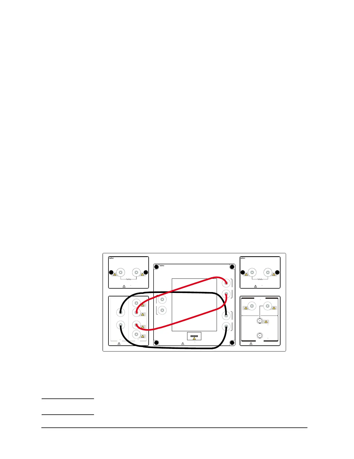
• Connection:
See Figure 2-5.
1. Connect a wire between the Low Force terminal and the low terminal of DUT.
2. Connect a wire between the Low Sense terminal and the low terminal of DUT.
3. Connect a wire between the High Force terminal and the high terminal of DUT.
4. Connect a wire between the High Sense terminal and the high terminal of DUT.
This connection is effective for all measurement performed by the modules connected
to the module selector Input terminals. Connection change is not required. The module
selector switching status is indicated by the Status indicator mounted on the front
panel. See Figure 2-6 and Table 2-6 on page 2-15.
The Guard terminals must be opened. You may extend it as close as possible to a DUT
terminal for reducing the leakage current of the extension cable.
Figure 2-5 Module Selector Connection Example
CAUTION Maximum current must be ± 30 A to prevent the module selector from performance
degradation and failure.
High Voltage Bias–Tee
Guard
Module Selector Output
Force
Sense
Guard
Sense
Force
1 MΩ
21
100 kΩ
HighLow
21
±3 kV Max±40 V Max
N1259A
Opt 022
±3 kV Max
Max: 6.4 W
±3 kV Max
Max: 9 W
N1259A
Opt 021
N1259A
Opt 010
Force
Sense
Force
Sense
Force
Sense
1
2
3
123
±3 kV Max
Inline Package Socket (3 Pin)
Kelvin Connection
MF CMU
DC Bias Input
±3 kV Max
High
Low
Force
±3 kV Max
±25 V Max
Guard

 Loading...


