1Introduction
40 Keysight N1913/1914A User’s Guide
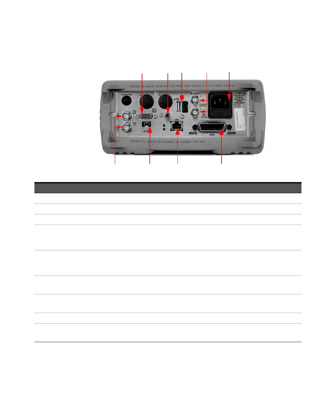
Rear Panel Connections
No. Connections
1 VGA Output (Option 201)
2 Ground Connector
3 USB Type A port
4 Recorder 1/2
Recorder output (two outputs are fitted to dual channel meters) connections are made via BNC connectors. This
output produces a DC voltage that corresponds to the power level of the channel input.
5AC Inlet
This power meter has an auto configuring power supply. This allows it to operate over a range of voltages without
manually being set to a certain voltage.
6 Trig In/Trig Out
Trigger input and output connections are made via BNC connectors.
7 USB Mini-B port
This USB port is used only for remote interface connection.
8LAN
9GPIB
This connector allows the power meter to be controlled remotely using the General Purpose Interface Bus.