Kinco FD5P AC series servo driver
册
Chapter 6 Operation modes and control modes
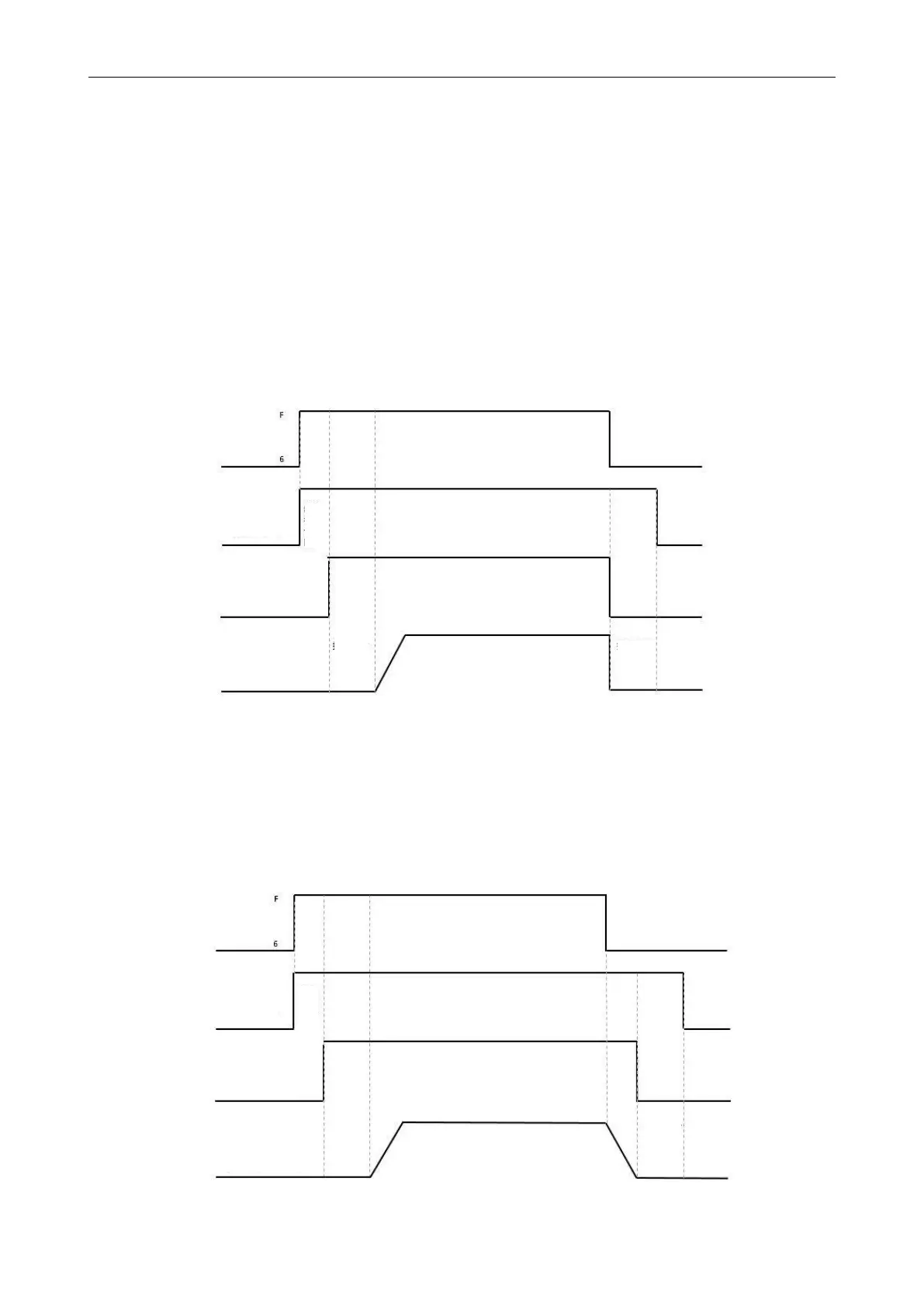
After the control word is written into the enable command, the servo motor is energized to lock the shaft,
and the driver outputs 24V DC to the brake after the relay pull-in delay for a certain period of time (brake
delay) to make the brake open as soon as possible. After the delay, the speed command takes effect and the
motor starts to run.
When the stop enable command is written in the control word, the control of the holding
brake is related to the set quick stop mode.
When the quick stop mode is 0 (uncontrolled stop), the drive will automatically switch to the
immediate speed mode (-3) and set the target speed to 0 internally to make the motor stop as
soon as possible, in the uncontrolled stop mode After the drive changes the target speed, it will
immediately cut off the 24V power supply to the brake. After the brake power is cut off and lasts
for a certain period of time (the brake delay), the drive actually enters the disabled state, and the
motor is powered off and the shaft is released.
Figure 6-15 Motor holding brake sequence when quick stop mode is 0
When the quick stop mode is 2 (quick stop deceleration stop), the drive automatically switches to
speed mode (3) and decelerates to stop at quick stop deceleration (60850020) when it is disabled.
Only after the drive judges that the effective target speed is zero speed , the drive will cut off the
24V brake power supply. After the brake power supply has been cut off for a certain period of
time (the brake delay time), the drive will enter the disabled state, and the motor will be
disconnected from the power supply.
Figure 6-16 Motor brake sequence when quick stop mode is 2
actual velocity
(uncontrolled stop)
actual velocity
(uncontrolled stop)
 Loading...

