Kinco FD5P AC series servo driver
册
Chapter5 KincoServo +, user guide
Note
DIN control word selection (2020.0F) is set to 0x2F by default. For the definition
of control word, please refer to Chapter 6.1
Position fine-tuning data in positive direction in active pulse mode
Position fine-tuning data in negative direction in active pulse mode
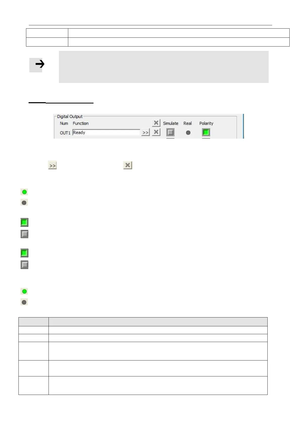
5.5.2 Digital outputs
Figure 5-10 Digital output
Function:Click to select Din function setting click to delete the DIN
function
Real:Shows the real digital input hardware status.
1 means “active”, logic status of the digital input is 1
0 means “inactive”, logic status of the digital input is 0.
Simulate: Simulates the digital input active hardware signal.
1 means the digital input is simulated as “active”, logic status 1.
0 means no impact on the digital input logic status. Polarity: Inverts the logic
status of the digital input.
1 means Internal is set to 1 by “active” signal.
0 means Internal is set to 1 by “inactive”
Internal: This is the result of Simulate, Real and Polarity via the logic formula:
Internal=(Real OR Simulate) XOR (NOT Polarity)
1 means “active”, logic status of the selected function is 1.
0 means “inactive”, logic status of the selected function is 0.
Table 5-3 Digital output functions
Table 5-3 Digital output function
Controller is ready to be enabled
In position mode, when the difference between the actual position and the target position is less than the target position
window (6067.00), and the duration is greater than or equal to the position window time (6068.00), the output position to
the function is displayed
When the absolute value of the actual velocity -ms (60F9.1A) is less than or equal to the zero velocity window (2010.18),
and the duration is greater than or equal to the zero velocity time (60F9.14), the zero velocity function is output
The motor brake control output signal can be used to connect an external relay that controls the motor lock. If the brake
motor is used, this function must be set, otherwise it will damage the motor. An effective output of green indicates that the
lock is opened, and an effective output of gray indicates that the lock is closed.
 Loading...

