Kinco FD5P AC series servo
10.2 RS485
Communication
10.2.1 RS485 Hardware wiring
The RS485 port of the FD5P series servo drive supports the MODBUS communication function,
which can be used to modify the internal parameters of the servo and monitor the servo status.
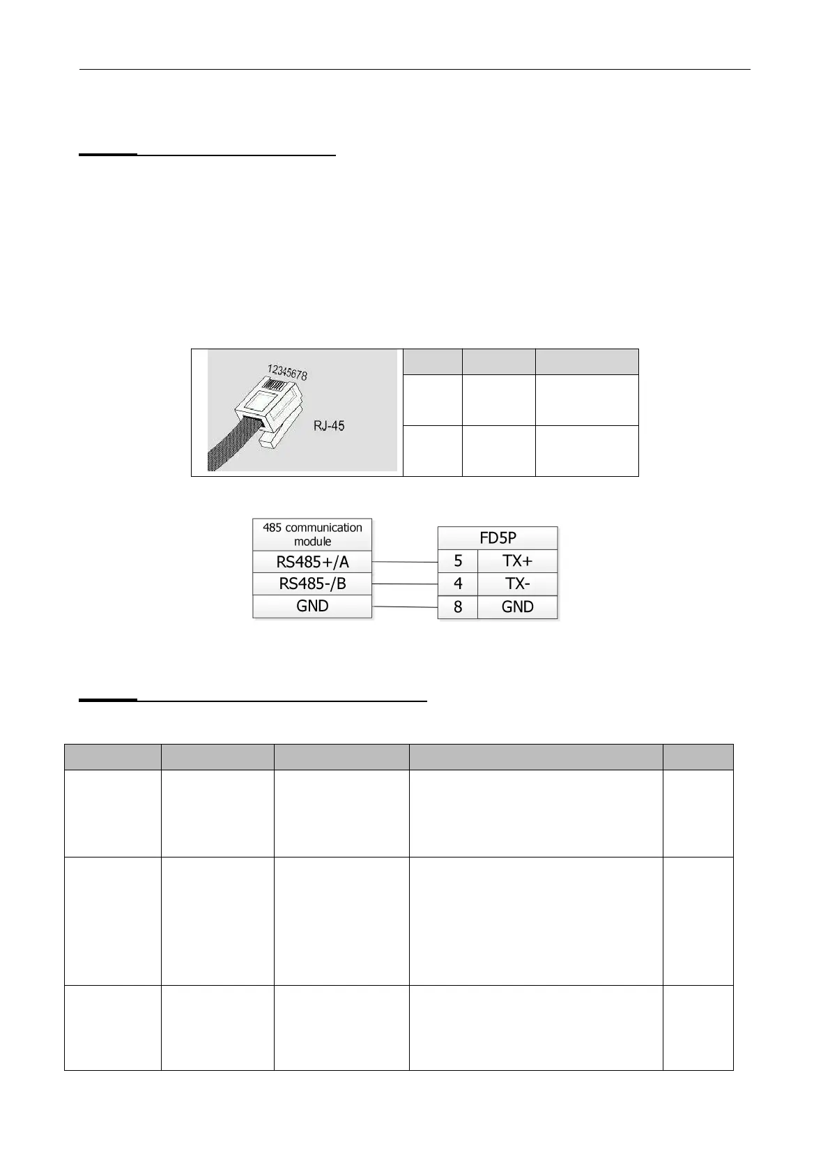
The communication line of the master station is connected to X4A (IN), and X14B (OUT) is
connected to the next slave device。Wiring is shown in Figure 10-2 and Figure 10-3.
Table 10-2 RS485 Communication port description
Figure 10-2 RS485 signal wiring
10.2.2 RS485 communication parameters
Table
10-3 RS485
communication parameters setting
Station No., to change this parameter, you
need to save it with the address d5.00 and
restart it later
。
The station number can be
changed by the DIP switch under the panel
.
Details refers to Chapter 3.8
Used to set the baud rate of RS485
value baud rate
1080————9600
540————19200
270————38400
90————115200
Note: need to save and restart.
0
:
us e Modbus communication
protocol
1 : use RS232 communication
protocol
Note: need to save and restart。

 Loading...
