Kinco FD5P AC series servo driver
Chapter 3 Installation and wiring
Purchase link of Kinco official Tmall store:
https://detail.tmall.com/item.htm?spm=a212k0.12153887.0.0.4d7c687
deB8shy&id=652422874770&skuId=4707119953745
3.4
External input and output connection(
X1
)
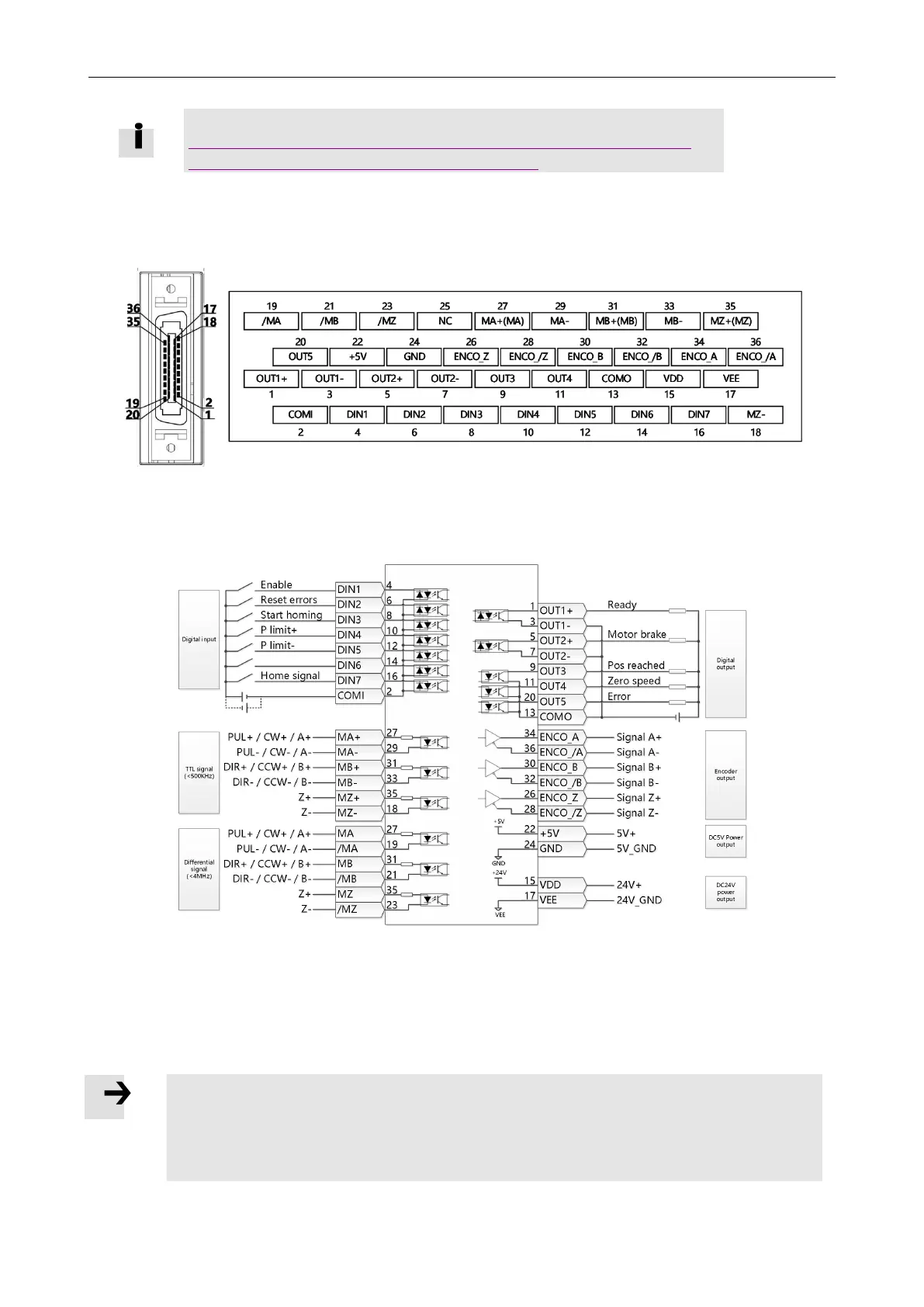
Figure 3-13 FD5P-LA/CA drive external input and output terminal pin diagram
Figure 3-14 FD5P-LA/CA Default definition of IO port of FD5P-LA/CA drive
Note
Figure 3-14 shows the X1 wiring of the FD5P-LA/CA driver's default IO function.
More IO functions can be defined by the digital panel or the upper computer
debugging software. For more details on IO features, see Chapter 5, Section 5.5.

 Loading...
