Kinco FD5P AC series servo driver
册
Chapter5 KincoServo +, user guide
5.6 Scope
In the operation process, if the operation effect of the equipment can not meet the
requirements, or other accidents occur, you can use the oscilloscope to analyze the problem.
Click the button in the software to turn on the oscilloscope.
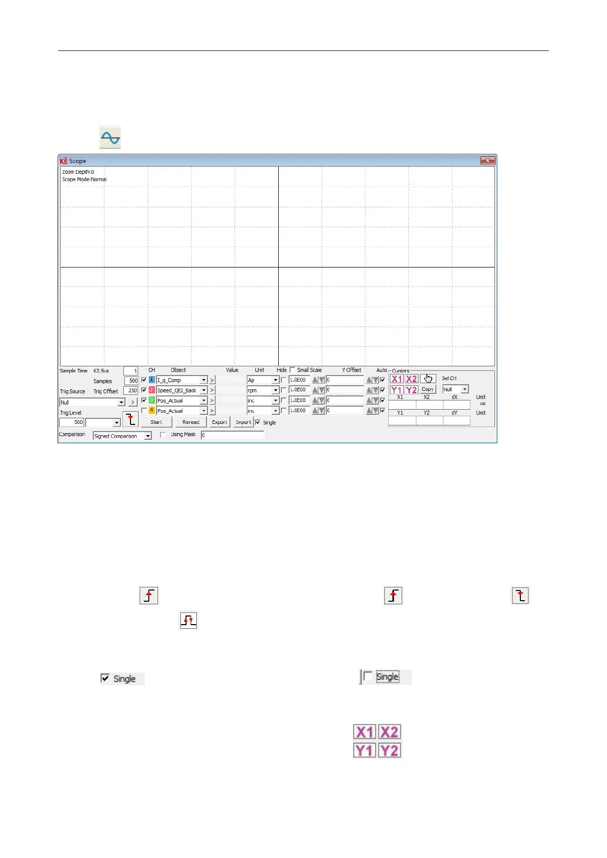
Figure
5-11
Scope window
Trig offset: Data collection period. If the value is set to 1, data is collected every 62.5us.
Samples:This parameter indicates how many data are collected during the sampling. If the value is set
to 500, 500 data are collected.
Trig offset:The number of samples before the trigger source is triggered.
Trig source and Trig level:The trigger condition is set in Figure 5-13 to start collecting data when
the effective target current q rises to 100DEC. DEC is the internal unit and can be switched to the
current unit.
Trigger edge: clicking could change it to rising edge trigger 、falling edge trigger or rising
and falling edge trigger .
Object: Maximum 64-bit length data can be taken in one sample, e.g.: 2 Int32 objects bit or 4 Int16
objects.
Single: means sample for one trigger event only;
means sample continuously.
Zoom in/ Zoom out the oscillogram:Hold down the right mouse button and drag the
mouse down to the right to zoom in, and to the upper left to zoom out.
Cursors:Up to 4 scope cursors can be selected by clicking
button. The scope
cursors appear in the oscillogram ,and select the channel you want to observe from the
Channel Selection drop-down menu.
 Loading...

