Kinco FD5P AC series servo driver manual
Chapter 1 Servo system model and
configuration description
Chapter 1 Servo system model and configuration
description
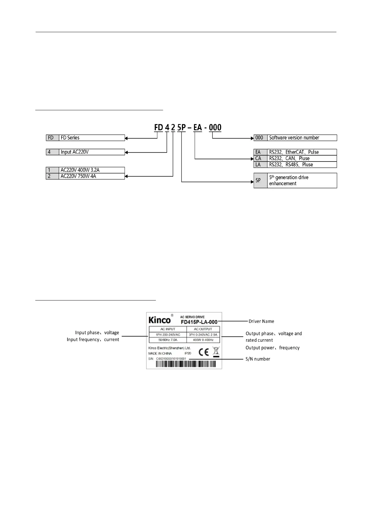
1.1 Description of product model
Figure 1-1 Drive naming rules
1.2 Drive nameplate description
Figure
1-2
Drive nameplate description

 Loading...
