Kinco FD5P AC series servo driver
册
Chapter 6 Operation modes and control modes
6.5 Pulse mode (-4)
In the pulse mode, the target velocity command is specified via the pulse input with gear ratio,
Please refer to Figure 4-4 in Chapter 4.3.2 for the wiring method in pulse mode. It can be debugged
by expanding the relevant parameters in the software.
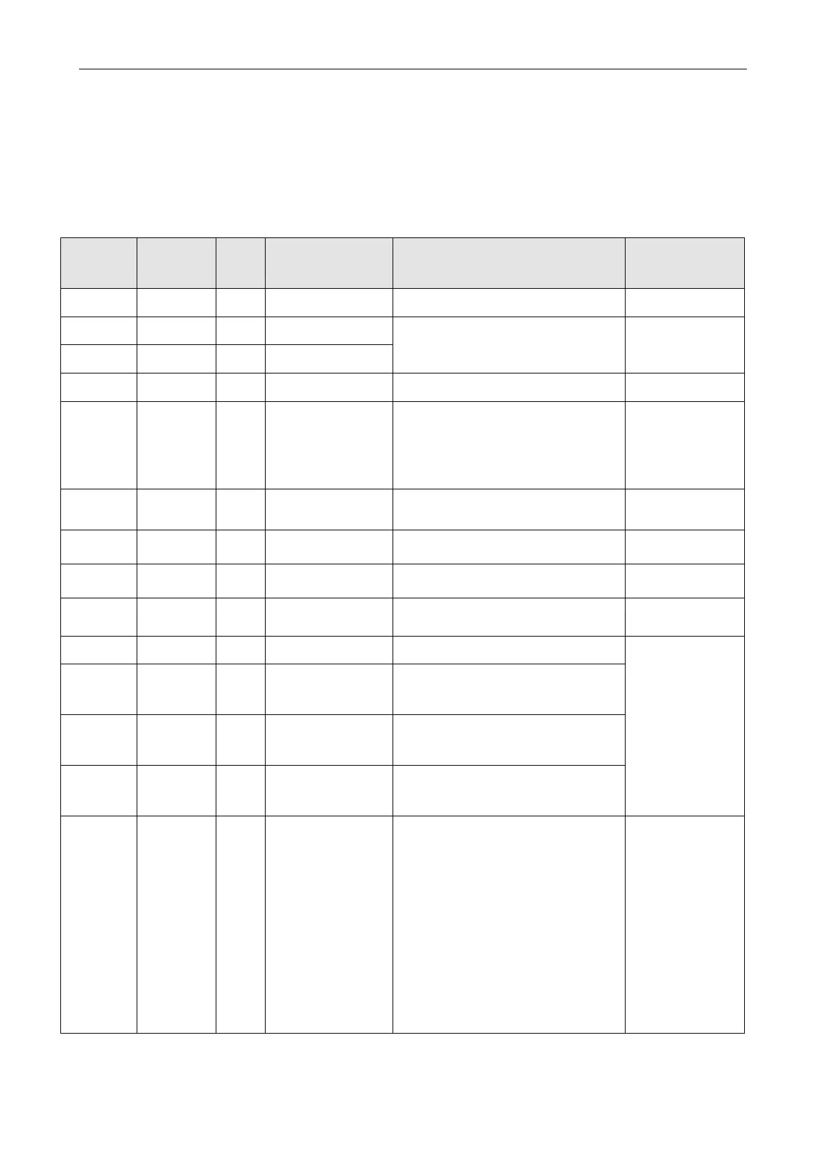
Table 6-16 Pulse Mode
Gear_ratio=Gear_Factor/Gear_Divider
Pulse train mode
0: CW / CCW
1: Pulse / direction
2: A / B (incremental encoder)
The main encoder port counts before
inputting pulse electronic gear
The main encoder port counts after inputting
pulse electronic gear
Pulse speed of spindle input(pulse/ms)
Speed after spindle input pulse gear ratio
(pulse/ms)
Frequency limit (inc/ms), if pulse count (in 1
ms) is greater than Frequency_Check, over
frequency error occurs.
Position fine-tuning is used to set the position
data to be fine-tuned in pulse mode, the unit
is inc, the default value is 0
Speed fine-tuning is used to set the speed
when performing position fine-tuning, the unit
is inc/ms, the default value is 0
CPLD Pulse Filter
Configuration
CPLD internal filter is used for pulse input
port, only for pulse signal with 50% duty
cycle, the filter frequency is:
0: 4MHz
1: 3.2MHz
2: 2MHz
3: 1.6MHz
4: 500KHz(Default)
5: 330KHz
6: 250KHz
7: 125KHz
Note: The filter frequency must be higher
than the Gear pre-pulse frequency

 Loading...
