Kinco FD5P AC series servo driver
册
Chapter5 KincoServo +, user guide
5.5 Digital IO function
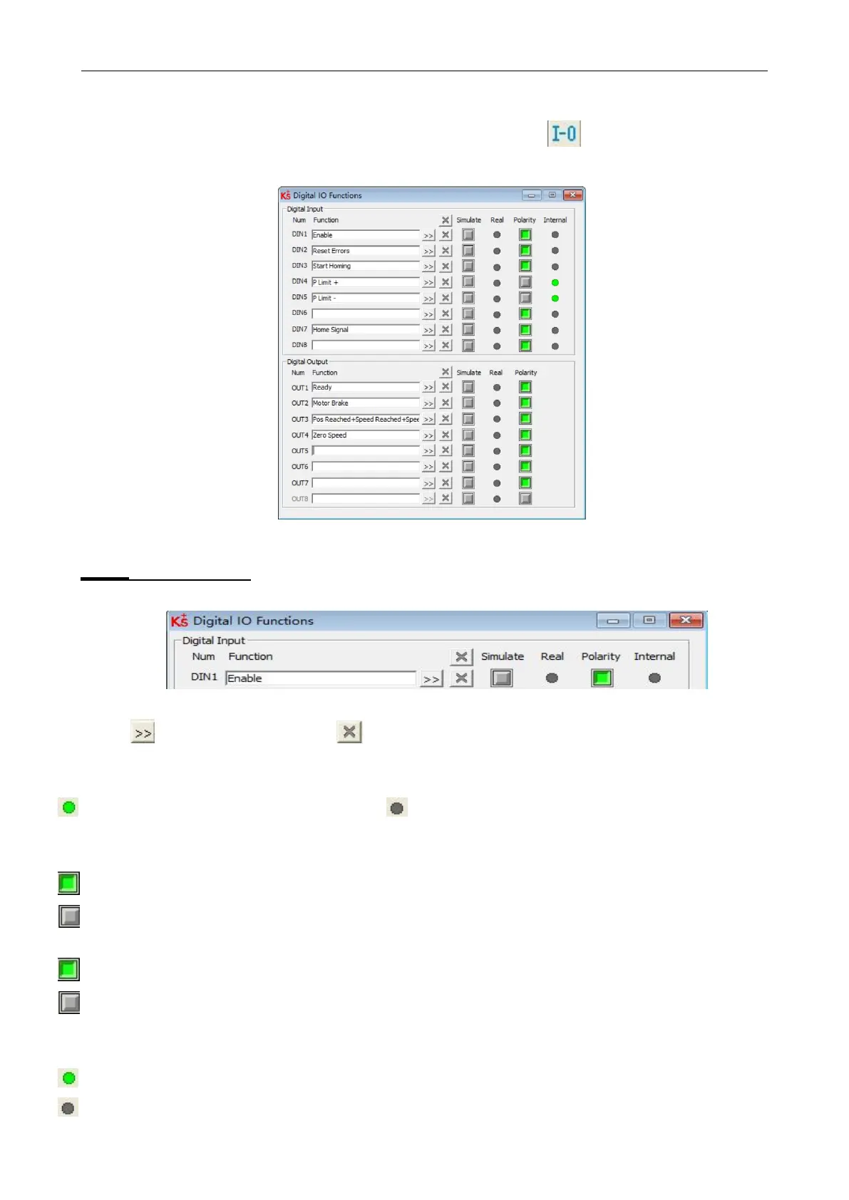
Click menu item Controller->Digital IO Functions or click the button
. The following window
appears. Function and polarity are shown. Shown as default function and polarity.
Figure 5-8 Digital IO
5.5.1 Digital inputs
Figure 5-9 Digital input
Function:Click to select Din function setting click
to delete the DIN
function
Real:Shows the real digital input hardware status.
1 means “active”, logic status of the digital input is 1. 0 means
“inactive”, logic status of the digital input is 0.
Simulate: Simulates the digital input active hardware signal.
1 means the digital input is simulated as “active”, logic status 1.
0 means no impact on the digital input logic status. Polarity: Inverts the logic
status of the digital input.
1 means Internal is set to 1 by “active” signal.
0 means Internal is set to 1 by “inactive”
Internal: This is the result of Simulate, Real and Polarity via the logic formula:
Internal=(Real OR Simulate) XOR (NOT Polarity)
1 means “active”, logic status of the selected function is 1.
0 means “inactive”, logic status of the selected function is 0.
 Loading...

