Kinco FD5P AC series servo driver
册
Chapter 6 Operation modes and control modes
Note
The full closed-loop control function occupies the pulse input port, and the drive
cannot use the pulse mode after using this mode to control.
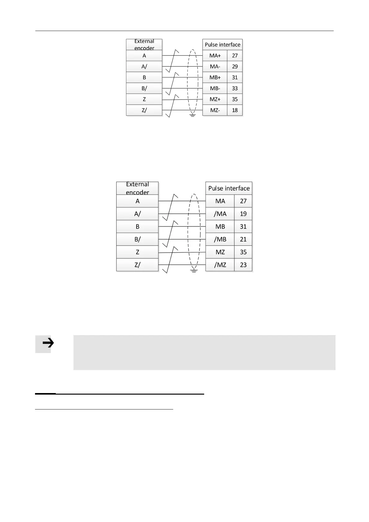
Figure 6-11 Fully closed loop control connection to regular pulse interface
②Use the high-speed pulse interface to connect the external encoder signal, the output frequency of the
external encoder is required to be below 4MHz, and the signal voltage range is 3.3-5VDC.
Figure 6-12 Full closed-loop control to connect high-speed pulse interface
6.6.1 Full closed loop control operation steps
Step 1:Add the full closed loop parameters
All the control parameters of the full closed loop need to be added to the window by the user. The
control parameters of the full closed loop are in group 250A of the object dictionary.You can add
full closed-loop parameters from the object dictionary to a window by right-clicking on any
window in the software and selecting Add.The added software window interface can be saved
as.kpjt file through the file F -- save in the software menu bar for subsequent debugging.
。
 Loading...

