Kinco FD5P AC series servo driver
册
Chapter 6 Operation modes and control modes
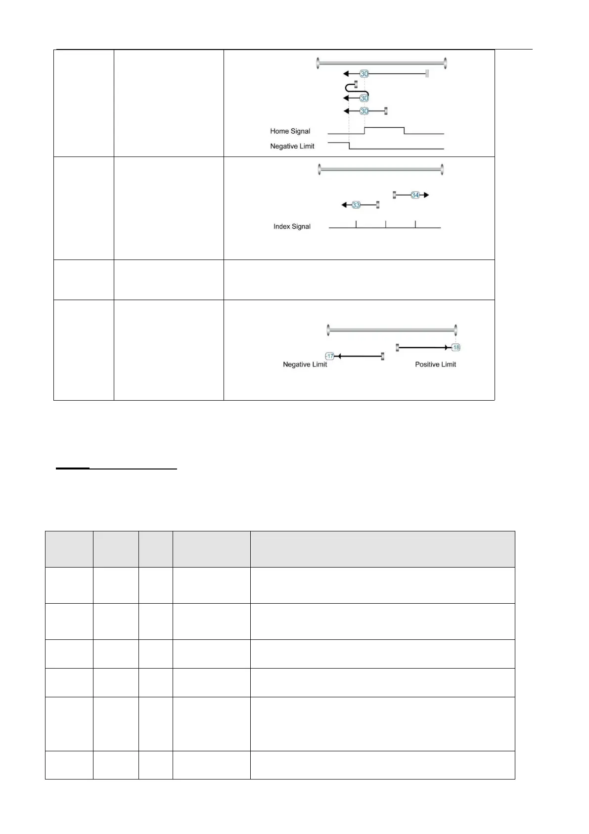
Homing with negative
position limit switch and
home switch
Homing to actual position
Homing via mechanical limit
6.8
Other functions
6.8.1 Limit function
In order to ensure that the motor runs within the stroke range allowed by the mechanical structure, the
motor can be prevented from overtravel running by inputting the limit signal.
Table 6-24 Limit setting
Define digital input DIN 4
。
Default value 0010
,
Indicates the definition of
the positive limit function
Define digital input DIN5
。
Default value 0020
,
Indicates the definition of
the negative limit function
Actual position when the digital input signal triggers the positive limit
Actual position when the digital input signal triggers the negative limit
The function of defining whether to alarm after the limit signal occurs
0
:
If the limit signal appears after homing, it will alarm
1: it will not alarm when the limit signal appears after homing
Positive setting of
soft limit
Soft limit positive polarity data setting

 Loading...
