injectors F (Fig. 6.7) .
2.
Insert electronic injector F into manifold T ,
being extra careful not to damage gasket
AB and direct it as indicated in Fig. 6.7 .
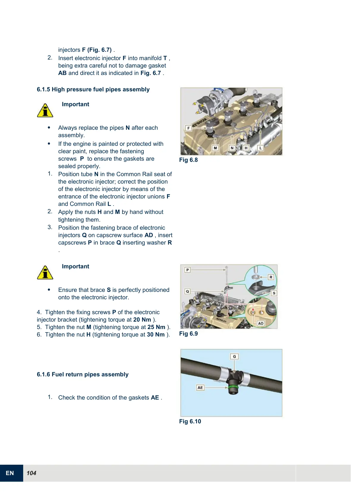
6.1.5 High pressure fuel pipes assembly
Important
Always replace the pipes N after each
assembly.
If the engine is painted or protected with
clear paint, replace the fastening
screws P to ensure the gaskets are
sealed properly.
1.
Position tube N in the Common Rail seat of
the electronic injector; correct the position
of the electronic injector by means of the
entrance of the electronic injector unions F
and Common Rail L .
2.
Apply the nuts H and M by hand without
tightening them.
3.
Position the fastening brace of electronic
injectors Q on capscrew surface AD , insert
capscrews P in brace Q inserting washer R
.
Important
Ensure that brace S is perfectly positioned
onto the electronic injector.
4. Tighten the fixing screws
P
of the electronic
injector bracket (tightening torque at
20 Nm
).
5. Tighten the nut
M
(tightening torque at
25 Nm
).
6. Tighten the nut
H
(tightening torque at
30 Nm
).

 Loading...


