1.
Perform the operations described in Par.
8.5.4 .
2.
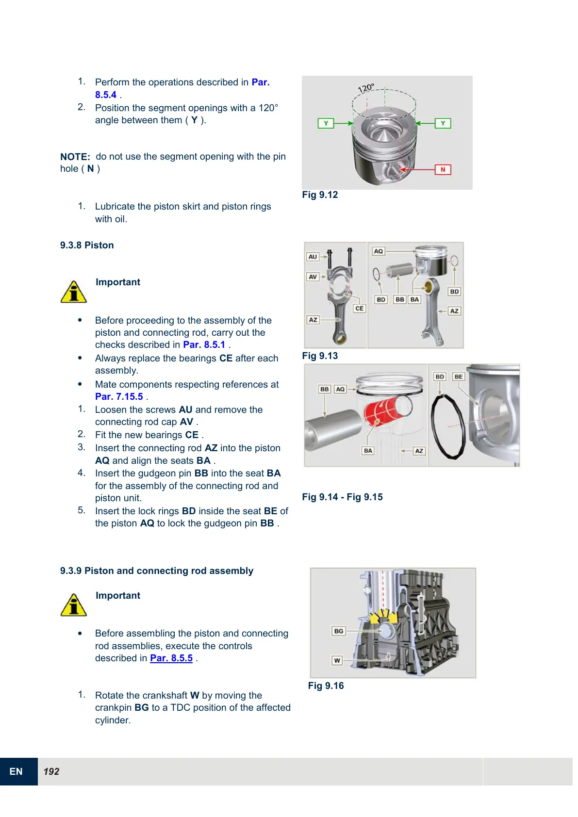
Position the segment openings with a 120°
angle between them ( Y ).
NOTE:
do not use the segment opening with the pin
hole (
N
)
1.
Lubricate the piston skirt and piston rings
with oil.
9.3.8 Piston
Important
Before proceeding to the assembly of the
piston and connecting rod, carry out the
checks described in Par. 8.5.1 .
Always replace the bearings CE after each
assembly.
Mate components respecting references at
Par. 7.15.5 .
1.
Loosen the screws AU and remove the
connecting rod cap AV .
2.
Fit the new bearings CE .
3.
Insert the connecting rod AZ into the piston
AQ and align the seats BA .
4.
Insert the gudgeon pin BB into the seat BA
for the assembly of the connecting rod and
piston unit.
5.
Insert the lock rings BD inside the seat BE of
the piston AQ to lock the gudgeon pin BB .
9.3.9 Piston and connecting rod assembly
Important
Before assembling the piston and connecting
rod assemblies, execute the controls
described in Par. 8.5.5 .
1.
Rotate the crankshaft W by moving the
crankpin BG to a TDC position of the affected
cylinder.

 Loading...


