1.
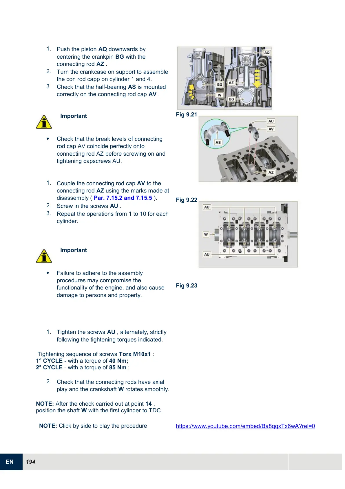
Push the piston AQ downwards by
centering the crankpin BG with the
connecting rod AZ .
2.
Turn the crankcase on support to assemble
the con rod capp on cylinder 1 and 4.
3.
Check that the half-bearing AS is mounted
correctly on the connecting rod cap AV .
Important
Check that the break levels of connecting
rod cap AV coincide perfectly onto
connecting rod AZ before screwing on and
tightening capscrews AU.
1.
Couple the connecting rod cap AV to the
connecting rod AZ using the marks made at
disassembly ( Par. 7.15.2 and 7.15.5 ).
2.
Screw in the screws AU .
3.
Repeat the operations from 1 to 10 for each
cylinder.
Important
Failure to adhere to the assembly
procedures may compromise the
functionality of the engine, and also cause
damage to persons and property.
1.
Tighten the screws AU , alternately, strictly
following the tightening torques indicated.
Tightening sequence of screws Torx M10x1 :
1° CYCLE - with a torque of 40 Nm;
2° CYCLE - with a torque of 85 Nm ;
2.
Check that the connecting rods have axial
play and the crankshaft W rotates smoothly.
NOTE: After the check carried out at point 14 ,
position the shaft W with the first cylinder to TDC.

 Loading...


