9.7.4 Valves
1.
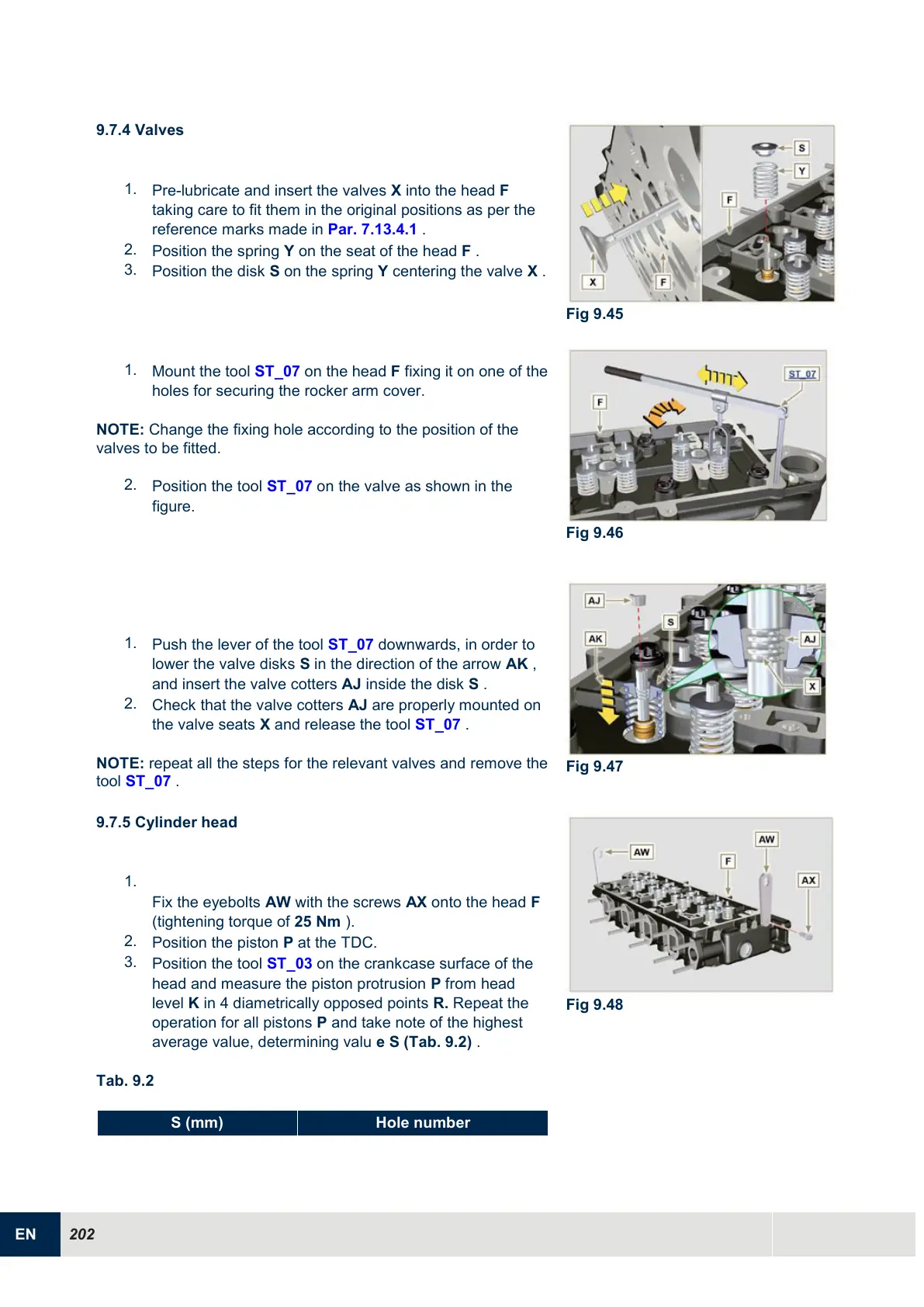
Pre-lubricate and insert the valves X into the head F
taking care to fit them in the original positions as per the
reference marks made in Par. 7.13.4.1 .
2.
Position the spring Y on the seat of the head F .
3.
Position the disk S on the spring Y centering the valve X .
1.
Mount the tool ST_07 on the head F fixing it on one of the
holes for securing the rocker arm cover.
NOTE: Change the fixing hole according to the position of the
valves to be fitted.
2.
Position the tool ST_07 on the valve as shown in the
figure.
1.
Push the lever of the tool ST_07 downwards, in order to
lower the valve disks S in the direction of the arrow AK ,
and insert the valve cotters AJ inside the disk S .
2.
Check that the valve cotters AJ are properly mounted on
the valve seats X and release the tool
ST_07 .
NOTE: repeat all the steps for the relevant valves and remove the
tool ST_07 .
9.7.5 Cylinder head
1.
Fix the eyebolts AW with the screws AX onto the head F
(tightening torque of 25 Nm ).
2.
Position the piston P at the TDC.
3.
Position the tool ST_03 on the crankcase surface of the
head and measure the piston protrusion P from head
level K in 4 diametrically opposed points R. Repeat the
operation for all pistons P and take note of the highest
average value, determining valu e S (Tab. 9.2) .
Tab. 9.2

 Loading...


