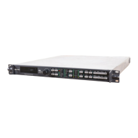
202 X75HD/X75SD Installation and Operation Manual
Appendix A: Cables and Pinouts
Analog Audio Connections
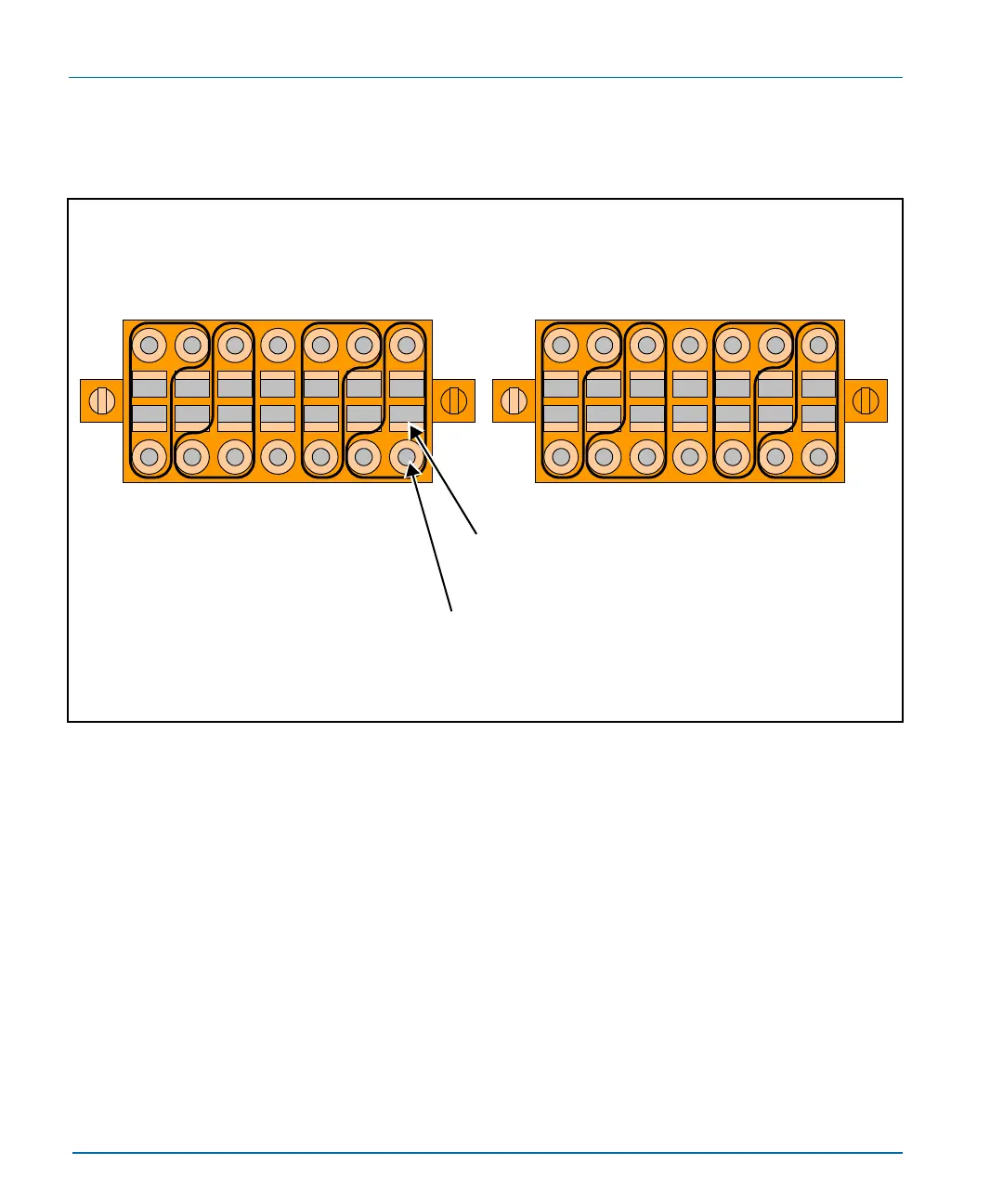
Figure A-1 shows the analog audio input and output terminal blocks.
Figure A-1. Analog Audio Input and Output Terminal Blocks
+ G + G + G +
- G - G - G -
CH1 CH2 CH3 CH4
+
-
GND GND GND
+
-
+
-
+
-
+ G + G + G +
- G - G - G -
CH1 CH2 CH3 CH4
+
-
GND GND GND
+
-
+
-
+
-
Analog audio input
(Left terminal from rear)
Analog audio output
(Right terminal from rear)
Step 1: Rectangular slot
Insert flathead screwdriver into a rectangular slot to open
a corresponding round connection point (above or below)
Step 2: Round Hole
Insert a stripped audio cable into a round hole and
remove the flathead screwdriver from the rectangular slot
to hold the cable.
(Note: The holes are polarized.)


 To Next Page