X75HD/X75SD Installation and Operation Manual 203
Appendix A: Cables and Pinouts
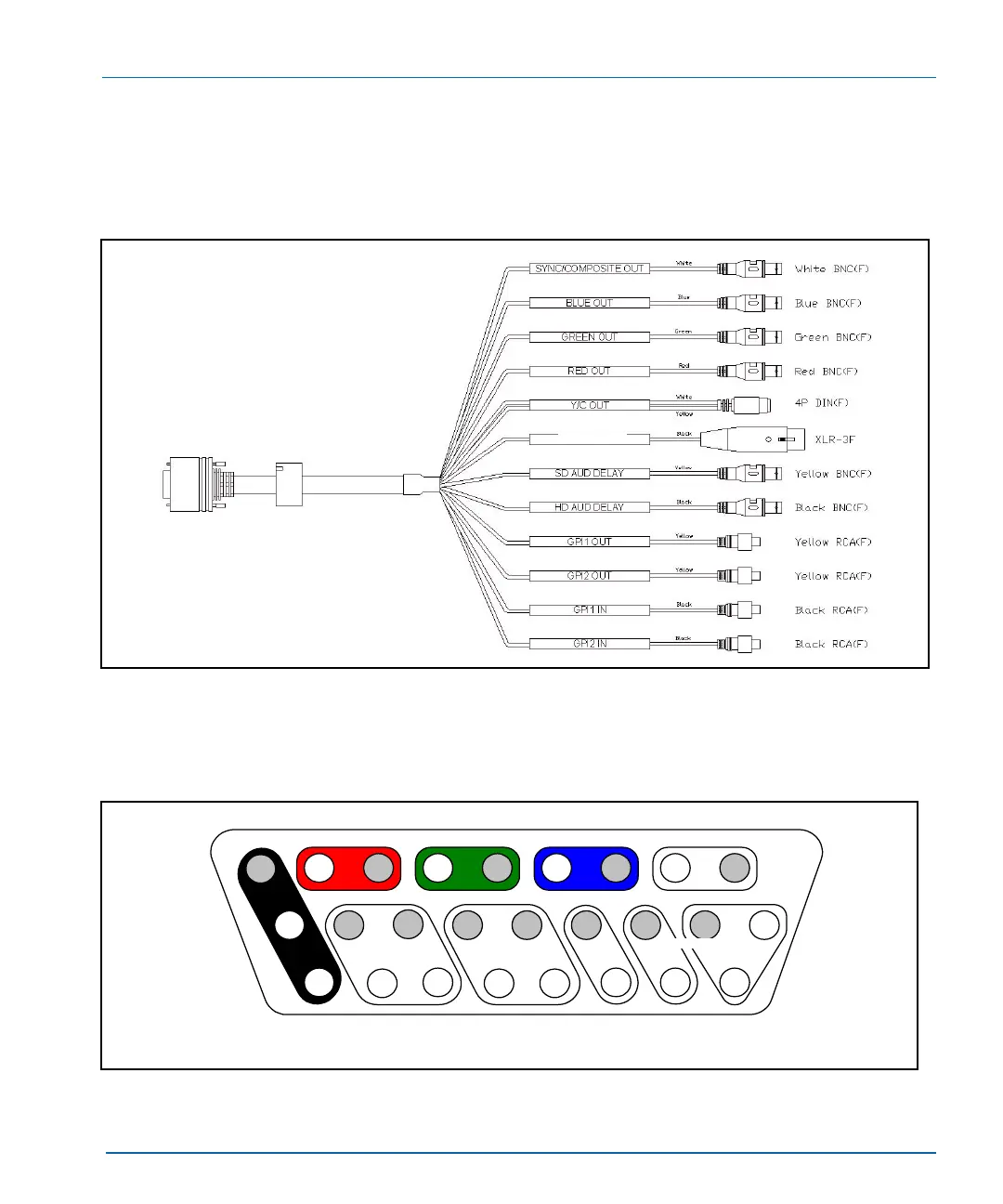
Multi I/O Cable (X75OPTCAB-MULTI)
Figure A-2 identifies the cable connectors available on the optional
multiple input/output X75OPTCAB-MULTI cable.
Figure A-2. X75OPTCAB-MULTI Cable Connectors
Figure A-3 shows the pinouts for the X75OPTCAB-MULTI DB-26M
connector.
Figure A-3. X75OPTCAB-MULTI I/O Connector Pinout
FUTURE USE
S G S G S G S G
GPI
in 2
G G G G G G +C
G
GPI
in 1
S S -Y
Pin 1
Pin 10
Pin 26
Pin 18
Pin 19
Pin 9
Timecode in
Red out Green out Blue out
Sync/composite
out
G
HD audio
delay
SD audio
delay
GPI inputs GPI outputs
GPI
op1
GPI
op2
S-video
out
Future use