X75SD/X75HD Installation and Operation Manual 9
Chapter 1: Introduction
Front and Rear Panels
Front Panel Description
Figure 1-1 and Figure 1-2 illustrate front blank, and front control
panels, respectively.
X75HD/X75SD units with a blank front panel, must be configured and
controlled remotely, using one of the following methods:
• Separate control panel such as an X75-RCP
• Local control panel on an X75HD/X75SD or DPS-575 unit
• CCS applications such as Pilot or Navigator
• Web server application using a common Web browser such as
Internet Explorer™ or Netscape™
• SNMP (Simple Network Management Protocol) and third-party
control software offered through Leitch CCS Protocol
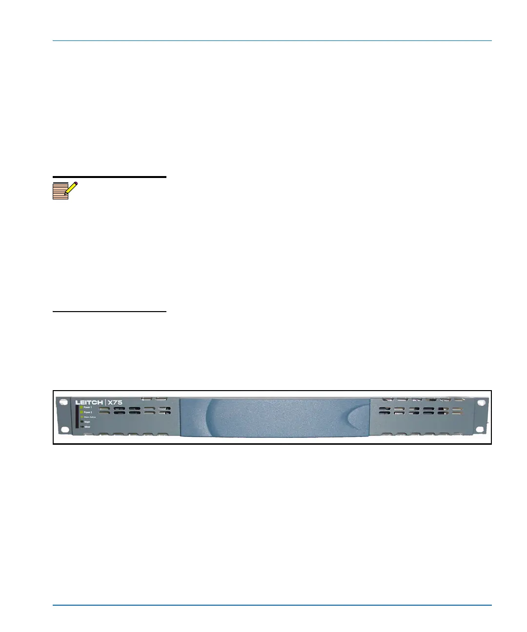
Blank front panels provide LEDs for alarm and status monitoring,
(including major and minor alarm LEDs), and status LEDs for power
and memory access.
Local and remote control panels contain LEDs that indicate alarm,
status, and configuration information. For more detailed information on
LCP controls and indicators, see the Control Panels for X75 Systems
Installation and Operation Manual.
Figure 1-1. Blank X75HD/X75SD Front Panel
Rear Panel Description
Figure 1-3 on page 11 illustrates a typical rear panel with all module
options installed. For more information on back panel connections, see
“Chapter 3: Module and Back Panel Descriptions” on page 51.
Note
DPS-575 units do not have the
Ctrl button found on
X75HD/X75SD models. Button
shortcuts on X75HD/X75SD
models that require the Ctrl
button are not accessible
remotely via a DPS-575 unit. In
these cases, the affected
parameters must be accessed
through the menu structure.
 Loading...