X75HD/X75SD Installation and Operation Manual 53
Chapter 3: Module and Back Panel Descriptions
Required Jumper Settings and Local Configuration
Setting Jumpers
To configure the impedances of analog audio inputs and outputs, you
must set specific jumpers.
Jumpers 1 through 12 are located at the rear of the module. Figure 3-2
on page 54 shows the location of the jumpers. See Table 3-1 for the
correct placement of the jumpers. The white triangle next to each
jumper indicates pin 1.
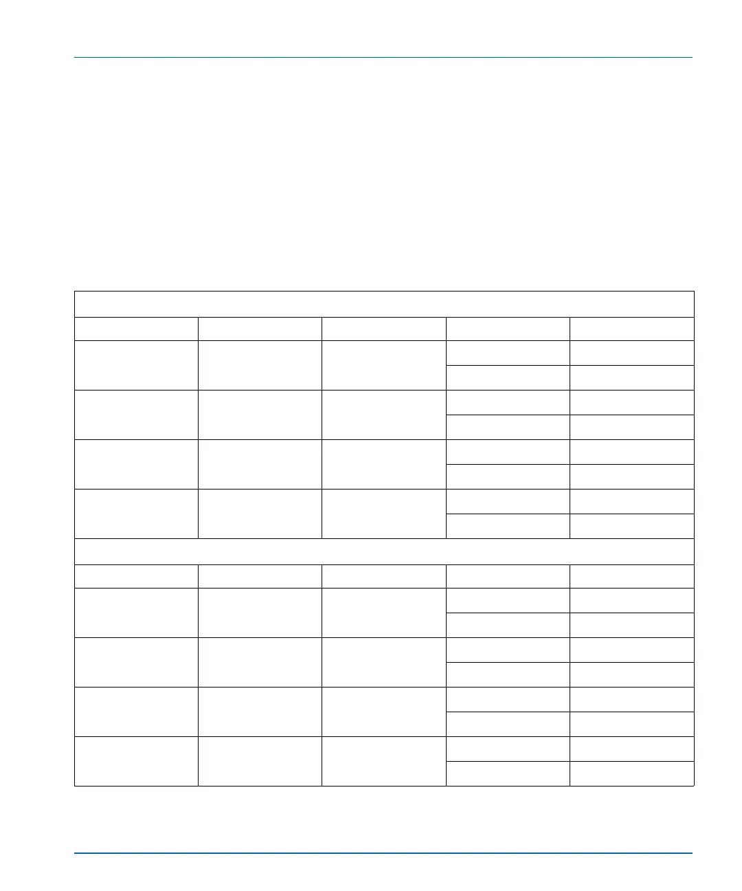
Table 3-1. Analog Audio Input and Output Impedance Jumper Settings
Input Settings
Input Number Jumper Numbers Channel Pin Numbers Setting
1 J5 Left (1A) 1 and 2 600Ω
2 and 3 100kΩ
2 J6 Right (1B) 1 and 2 600Ω
2 and 3 100kΩ
3 J7 Left (2A) 1 and 2 600Ω
2 and 3 100kΩ
4 J8 Right (2B) 1 and 2 600Ω
2 and 3 100kΩ
Output Settings
Output Number Jumper Numbers Channel Pin Numbers Setting
1 J1 and J9 Left (1A) 1 and 2 600Ω
2 and 3 66Ω
2 J2 and J10 Right (1B) 1 and 2 600Ω
2 and 3 66Ω
3 J3 and J11 Left (2A) 1 and 2 600Ω
2 and 3 66Ω
4 J4 and J12 Right (2B) 1 and 2 600Ω
2 and 3 66Ω