272 X75HD/X75SD Installation and Operation Manual
Appendix C: Servicing
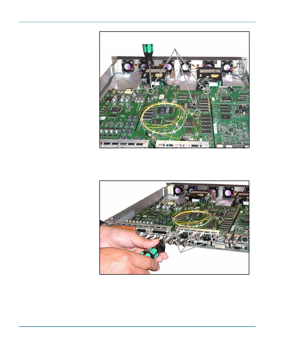
Figure C-14. Securing the Module to the Main Board
8. Screw the back panel into place using the screws removed in step 2.
Figure C-15. Securing the Back Connector to the Frame
9. Replace the chassis cover using the original screws. See page 261
for more information on replacing the cover.
Securing the module to the main board
Screw the module to the main board via
three standoffs.
Securing the back connector to the
frame
Screw the back connector to the frame
in three locations.