4.21 P2P Setting
The P2P function is used to share input and output devices between multiple inverters. To enable
P2P setting, RS-485 communication must be turned on .
Inverters connected through P2P communication are designated as either a master or slaves . The
Master inverter controls the input and output of slave inverters. Slave inverters provide input and
output actions. When using the multi-function output, a slave inverter can select to use either the
master inverter’s output or its own output. When using P2P communication, first designate the
slave inverter and then the master inverter. If the master inverter is designated first, connected
inverters may interpret the condition as a loss of communication.
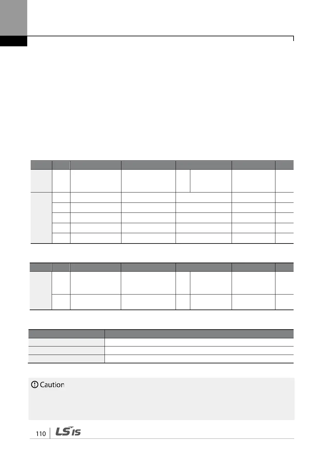
Master Parameter
CM 95
Communication
Int 485 Func 1 P2P Master
0–3
-
US
80 Analog input1 P2P In V1 0
0–12,000
%
81 Analog input2 P2P In I2 0
-12,000–12,000
%
82 Digital input P2P In DI 0
0–0x7F
bit
85 Analog output P2P Out AO1 0
0–10,000
%
88 Digital output P2P Out DO 0
0–0x03
bit
Slave Parameter
CM
95
Communication
Int 485 Func 2 P2P Slave
0–3
-
96
P2P OUT Sel 0 No
0–2
bit
P2P Setting Details
Set master inverter to 1(P2P Master), slave inverter to 2(P2P Slave).
Input data sent from the slave inverter.
US.85, 88 P2P Output Data
Output data transmitted to the slave inverter.
• P2P features work only with code version 1.00, IO S/W version 0.11, and keypad S/W version 1.07
or higher versions.
•
Set the user sequence functions to use P2P features..

 Loading...


