LumaSMART
®
User Manual DNP3 Protocol Testing • 129
The relay entries start at Number 16, consist of 16 groups of 5 consecutive entries showing each of the Relay
Control Values. Reference Relay Setup
in Section 5.2.1 for more information. The entries for each group, in order,
are:
• Configuration (Enable/Normally Energized/ Normally Deenergized)
• Alarm Setpoint Temperature
• Restore Setpoint Temperature
• Logic (Or/Avg)
• Temperature Channel Inputs for Relay
In the following example we will set the Control for Relay #6 as follows:
• Normally Deenergized
• Alarm Setpoint of 35 °C
• Restore Setpoint of 25 °C
• Or logic
• Temperature Channels inputs 5, 6 and 7
To change a value:
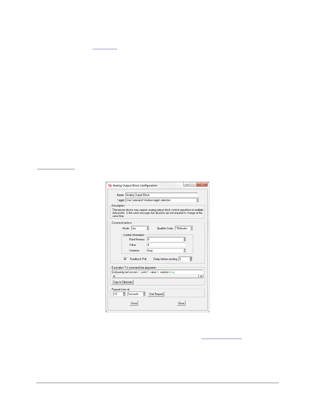
1. Open the command Analog Output Block, the following window will appear:
Analog Output Block
2. Set the Target to Use Command Window target selection.
3. Set the Point Number to the desired value to change (see Section 8.8 DNP3 Resister Map
).
4. Set the Variation to Short.
5. Set the Value to the desired value.
6. Press Once.

 Loading...