Manitowoc Published 11-06-15, Control # 040-13 2-9
2250 SERVICE/MAINTENANCE MANUAL HYDRAULIC AND AIR SYSTEMS
Table 2-8
Split Flange Leakage
SAE Flare Connection
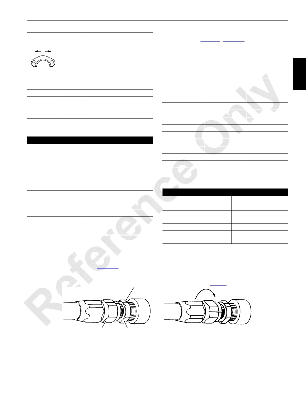
1. Tighten nut finger tight until sealing surfaces touch.
2. Mark a line (use felt pen or marker) on adapter and
extend it onto connector nut (Figure 2-9
, View A).
3. Using wrenches, tighten connector nut the number of
flats shown in Table 2-9
(Figure 2-9, View B).
4. Misalignment of marks will show how much nut has
been tightened, and best of all that it has been tightened.
Table 2-9
SAE 37° Flare Tightening
Table 2-10
SAE 37° Flare Leakage
1-9/16 -08 175 – 225 20 – 25
2 -12 300 – 400 34 – 45
2-1/4 -16 500 – 600 57 – 68
2-5/8 -20 750 – 900 85 – 102
3-1/8 -24 1400 – 1600 158 – 181
3-13/16 -32 2400 – 2600 271 – 294
Causes Cures
Flanges not tight Tighten bolts evenly to proper
torque.
Flanges tightened
unevenly causing
extrusion of o-ring
Replace o-rings. Tighten bolts
evenly to proper torque.
O-ring cut Replace
O-ring wrong size Replace with proper size
Sealing surfaces not
smooth; scratched or
gouged
Repair if possible or replace
parts
Sealing surfaces dirty Clean
Flanges keep getting
loose in service
Use SAE grade 5 bolts or
better. Retighten bolts after
system is hot.
A Dimension
inch
Flange
Size
Torque
in-lb N•m
Connector Nut
Size
(inch across
flats)
Fitting Size
Adapter Flats
to Rotate
9/16 -04 2-1/2
5/8 -05 2-1/2
11/16 -06 2
7/8 -08 2
1 -10 1-1/2 – 2
1-1/4 -12 1
1-1/2 -16 3/4 – 1
2 -20 3/4 – 1
2-1/4 -24 1/2 – 3/4
Causes Cures
Joint loose Tighten properly
Sealing surfaces dirty Clean
Sealing surfaces not smooth;
scratched or gouged
Replace faulty parts.
Sealing surfaces cracked Replace faulty parts.
SAE 45° parts used with SAE
37° parts
Use only SAE 37°parts.
View B
S108
FIGURE 2-9
View A
Connector
Nut
Adapter
Line
Turn connector nut required number
of flats (see Table 2-7
).
 Loading...


