BOOM 2250 SERVICE/MAINTENANCE MANUAL
4-16
Published 11-06-15, Control # 040-13
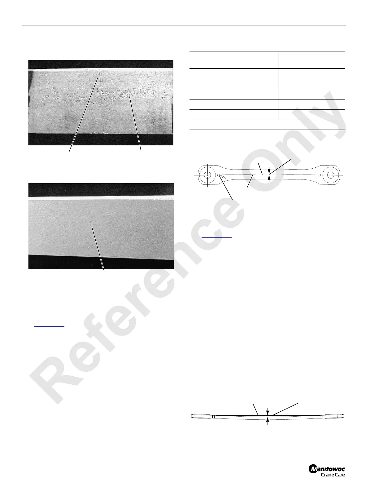
Straightness
See Figure 4-17 for the following procedure.
1. Stretch a line (string or wire) from pin storage hole at one
end of strap.
2. Stretch line as tight as possible and tie it off at other end.
3. Mark strap center line. Do not use center punch!
4. If string does not align with center line, measure
distance from center line to line.
5. If deviation from straight is greater than maximum
allowed, remove strap from service.
Flatness
See Figure 4-18 for the following procedure.
1. Lay strap on a flat surface. Do not block or the strap
may sag!
2. Stretch a line (string or wire) across top surface of strap
from pin storage hole at one end of strap.
3. Stretch line as tight as possible and tie it off at other end.
4. Check that line touches top surface of strap at all points
along its length.
5. If string does not touch strap, measure distance from
line to strap.
If deviation from straight is greater than maximum
allowed, remove strap from service.
6. Remove line. Turn strap over.
7. Repeat steps 1-5 above.
Not Acceptable
Abrasion from handling
with chain exceeds allowable limit.
Acceptable
Surface is relatively smooth; within allowable limit.
Not Acceptable
Surface is badly pitted;
exceeds allowable limit.
P325
P326
Corrosion or Abrasion
FIGURE 4-16
Strap Length
(L)
Maximum Deviation
Allowed
5 to <10 ft (1,5 to <3,0 m) 0.060 in (1,5 mm)
10 to <20 ft (3,0 to <6,1 m) 0.125 in (3,2 mm)
20 to <30 ft (6,1 to <9,1 m) 0.125 in (6,4 mm)
30 to <40 ft (9,1 to <12,2 m) 0.375 in (9,5 mm)
40 to <50 ft (12,2 to <15,2 m) 0.50 in (12,7 mm)
< = less than
Pin Storage
Hole (typical)
Center line
String
Deviation
from Straight
A1086
Straightness (gradual
or sweeping bend)
FIGURE 4-17
Distance between
Line and Strap
Line
A1086
Flatness (includes twisted straps)
FIGURE 4-18
 Loading...


