ELECTRIC SYSTEM 2250 SERVICE/MAINTENANCE MANUAL
3-2
Published 11-06-15, Control # 040-13
CIRCUIT BREAKER AND FUSE ID
General
This section identifies the fuses and circuit breakers.
Fuses are mounted in the fuse junction box located in the
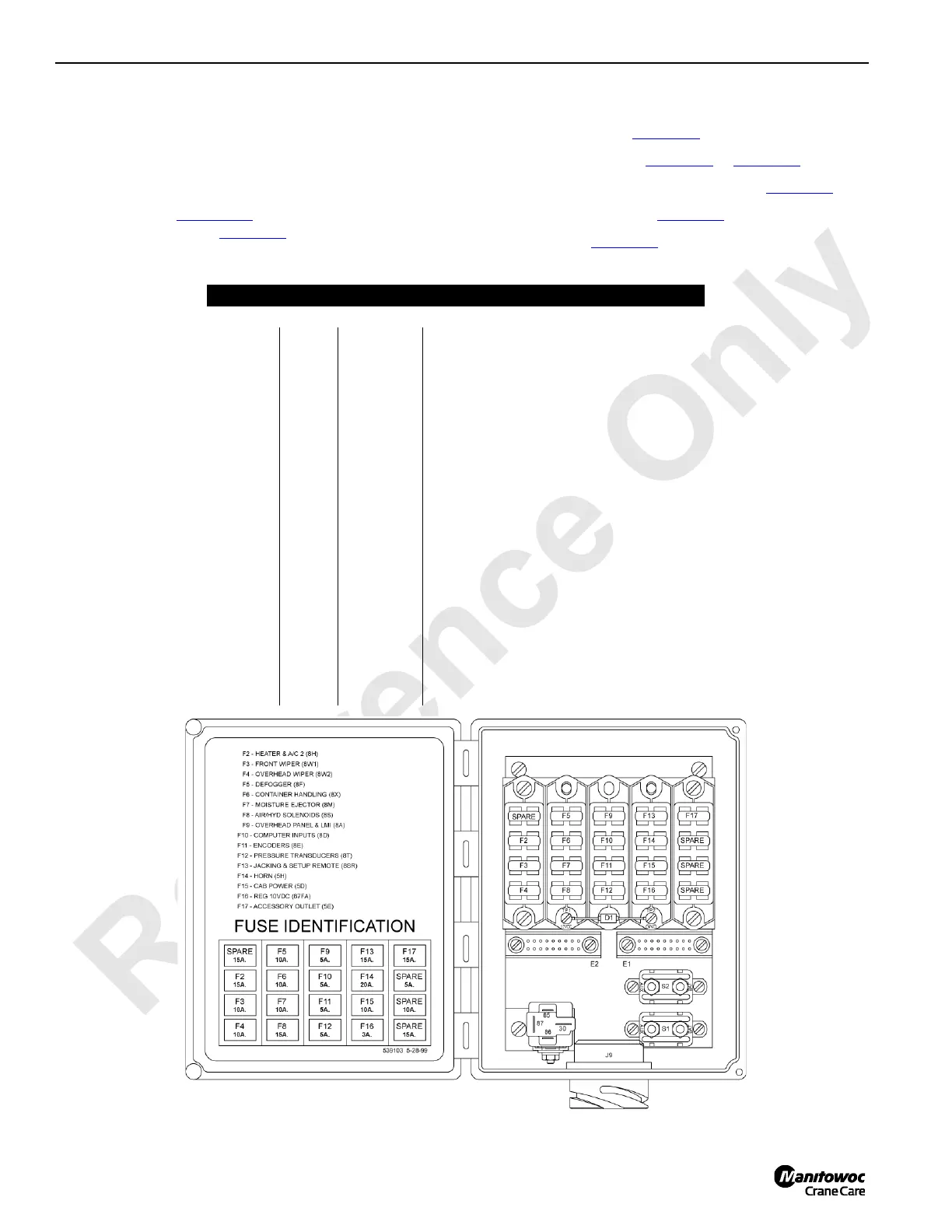
operator’s cab, Figure 3-1
or the CRANESTAR TCU
Harness at the batteries, Figure 3-8
.
Circuit breakers are mounted in the following locations:
• Fuse Junction Box, Figure 3-1
• Engine Junction Box, Figure 3-4 or Figure 3-5
• Cold Weather Package Junction Boxes, Figure 3-6
• MAX-ER Junction Box, Figure 3-7
• Power Plant, Figure 3-8
Fuse Amps Wire No. Description of Items Protected
Circuit Breaker and Fuse Junction Box Located in Operator’s Cab
F2 15 8H Heater and A/C
F3 10 8W1 Front Wiper
F4 10 8W2 Overhead Wiper
F5 10 8F Defogger
F6 10 8X Container Handling
F7 10 8M Moisture Ejector
F8 15 8S Air/Hydraulic Solenoids
F9 5 8A Overhead Panel and LMI
F10 5 8D Computer Inputs
F11 5 8E Encoders
F12 5 8T Pressure Transducers
F13 15 8SR Jacking and Setup Remote
F14 20 5H Horn
F15 10 5D Cab Power
F16 3 87FA 10VDC Regulated Power Supply
F17 15 5E Accessory Outlet
S1 50 CB 8P1 12 VDC to Programmable Controller
S2 40 CB 58 Air Conditioning and Accessory
2
6
8
4
0
8
FIGURE 3-1
 Loading...


