Manitowoc Published 11-06-15, Control # 040-13 7-21
2250 SERVICE/MAINTENANCE MANUAL POWER TRAIN
Cummins N14 – C525 Engine
General
The throttle assembly consists of an electronic control
module (ECM) on the engine, a hand throttle controller in the
left console, a foot pedal on the cab floor, an analog
converter board, associated linkage, and electrical
connections.
A reach rod in the right console connects the foot pedal to
the lever on the foot throttle controller. An electric cable
connects the hand throttle controller in the left control
console to the foot throttle controller.
Foot Throttle Linkage Adjustment
See Figure 7-24 for the following procedure.
1. Install spring clip (1) and rod end (2) on controller lever
at dimension shown in Figure 7-24
, View A and securely
tighten jam nut (3).
2. Insert a 3/16 in (5 mm) thick shim or piece of floor mat
between foot pedal and cab floor.
3. Press foot pedal down fully to high idle position against
shim or floor mat.
4. Adjust reach rod (4) and rod end (5) so controller lever is
rotated fully to high idle position. Securely tighten jam
nuts (6) to lock adjustment.
NOTE: Controller has internal stops at high and low idle.
5. Release foot pedal to low idle position.
6. Adjust return springs so there is sufficient force to raise
pedal and rotate controller lever to low idle.
7. Adjust pedal stop screw (7). Screw must be tight against
cab floor and there must be 1/8 in (31 mm) gap between
pin (9) and rear end of slot in rod end (5). Securely
tighten jam nut (8).
8. With foot pedal in low idle position, distance from top of
pedal to cab floor should be 3-15/16 in (100 mm).
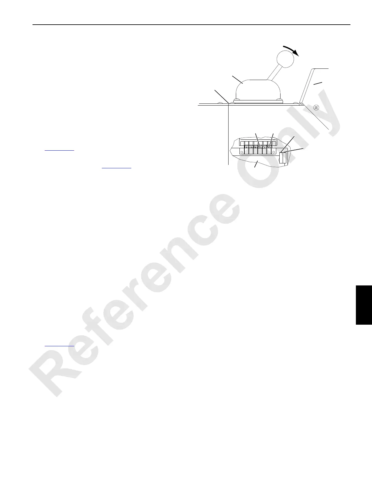
Engine Speed Calibration
See Figure 7-26 for the following procedure.
Engine speed is calibrated by the converter board mounted
in the left console near the hand throttle controller. This
board converts 0 – 10 VDC analog signal to 0 – 5 VDC
analog signal.
High and low idle engine speeds were calibrated at the
factory and should not need further attention. Calibration is
required if parts (controller, converter board, linkage) is
replaced.
1. Stop engine.
2. Remove cover plate and hand throttle controller from left
console. Move to side for access to converter board. Be
careful not to damage electric wires.
3. Connect voltmeter to 0 and 68K terminals on converter
board.
4. Turn cab power switch ON and set engine run/stop
switch to run to supply power to converter board. Do not
start engine.
5. Move hand throttle to minimum (low idle) position.
6. Adjust threshold potentiometer for output voltage of 0.60
– 0.70 VDC.
7. Move hand throttle to maximum (full throttle) position.
8. Adjust span potentiometer for output voltage of 3.90 –
4.00 VDC.
9. Recheck low and high idle settings; refine adjustments if
necessary.
10. Calibrate throttle settings to the electronic control
module (ECM) on the engine:
a. Leave run/stop switch in run position.
b. Operate hand throttle from low idle to high idle
position three times.
c. Turn run/stop switch to stop position.
11. Remove voltmeter and start engine.
FIGURE 7-26
Cover
Threshold
Potentiometer
Left
Console
Span
Potentiometer
0
68K
A974
Low Idle
Main Engine
Converter Board
Hand
Throttle
Controller

 Loading...


