POWER TRAIN 2250 SERVICE/MAINTENANCE MANUAL
7-24
Published 11-06-15, Control # 040-13
Test Voltages
The following test voltages are provided for troubleshooting
purposes and are measured at the terminal strip in junction
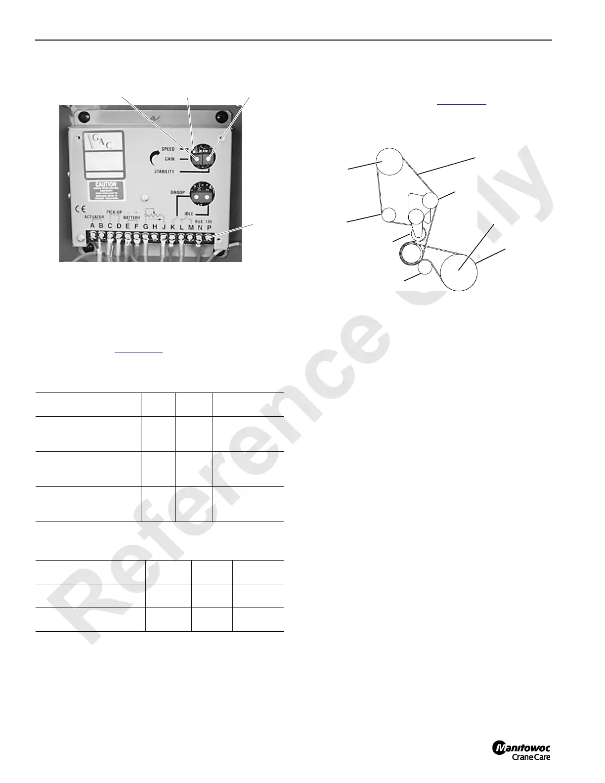
box on the engine (Figure 7-27
).
Table 7-5
DC Voltage
Table 7-6
AC Voltage
ENGINE BELT ROUTING — TIER 4 ENGINE
ONLY
Engine belt routing is shown in Figure 7-28 to help service
personnel when installing a new fan belt.
Operating Condition
Wire
No.
Term.
No.
VDC Reading
to Ground
Cab Power Switch ON
Run/Stop Switch - RUN
68L
68J
68K
G
J
L
0.005
5.880
3.848
Engine at Low Idle
(1,000 rpm)
68L
68J
68K
G
J
L
0.007
5.870
3.812
Engine at High Idle
(2,100 rpm)
68L
68J
68K
G
J
L
0.027
5.070
0.219
Operating Condition
Wire
No.
Term.
No.
VAC
Reading
Engine at Low Idle
(1,000 rpm)
24 and 0 C to D 6.580
Engine at High Idle
(2,100 rpm)
24 and 0 C to D 7.480
FIGURE 7-27
Gain
Adjustment
P855
Speed
Adjustment
Stability
Adjustment
Junction Box on Front of Engine
Terminal
Strip
FIGURE 7-28
Looking at Engine
from Fan End
Belt #1
Belt #2
Water
Pump
Alternator
Crankshaft
Fly Wheel
Tensioner
Tensioner
Tensioner
 Loading...


