HYDRAULIC AND AIR SYSTEMS 2250 SERVICE/MAINTENANCE MANUAL
2-34
Published 11-06-15, Control # 040-13
Every 6,000 hours or 36 months
Rebuild the air dryer including the desiccant cartridge.
The desiccant change interval may vary from crane to crane.
Although typical desiccant cartridge life is three years, many
will perform adequately for a longer period of time. In order to
take maximum advantage of desiccant life and assure that
replacement occurs only when necessary, it is important that
Operation and Leakage tests be performed.
AIR DRYER MAINTENANCE (PAST
PRODUCTION)
Description
See Figure 2-35 for the following procedure.
The air dryer is a filtering unit that cleans and dries the air
delivered to the air system by the air compressor.
Compressed air enters the air dryer where oil, water and
solid contaminants are removed and collected in a sump. Air
then flows up through the air dryer where any remaining
moisture is removed before the air enters the air tank. All
contaminants and any air remaining in the air dryer are then
discharged through an unloader valve during the
compressor cutout cycle.
Operation
Compressor Cut-In
See Figure 2-36 for the following procedure.
1. When pressure in the air tanks drops to the cut-in
pressure, the compressor unloader valve closes.
2. The compressor unloader valve then exhausts the air
from the pilot lines. This action closes the air dryer
unloader valve and signals the compressor to start
compressing air.
NOTE: For operation of moisture ejector, see Moisture
Ejector Valve Maintenance topic in this section.
3. Air from the compressor enters the air dryer where oil,
water and other solid contaminants are removed and the
air is dried.
4. The air flows through the check valve in the top of the air
dryer and into the air tanks.
Compressor Cut-Out
See Figure 2-36 for the following procedure.
1. When pressure in the air tanks reaches the cut-out
pressure, the compressor unloader valve opens. This
action signals the compressor to stop compressing air.
NOTE: The check valve in the top of the air dryer closes to
prevent the air in the system from exhausting
through the air dryer unloader valve.
2. Pressure in the pilot line to the air dryer unloader valve
causes it to open, allowing air, oil, water and dirt to
discharge from the air dryer.
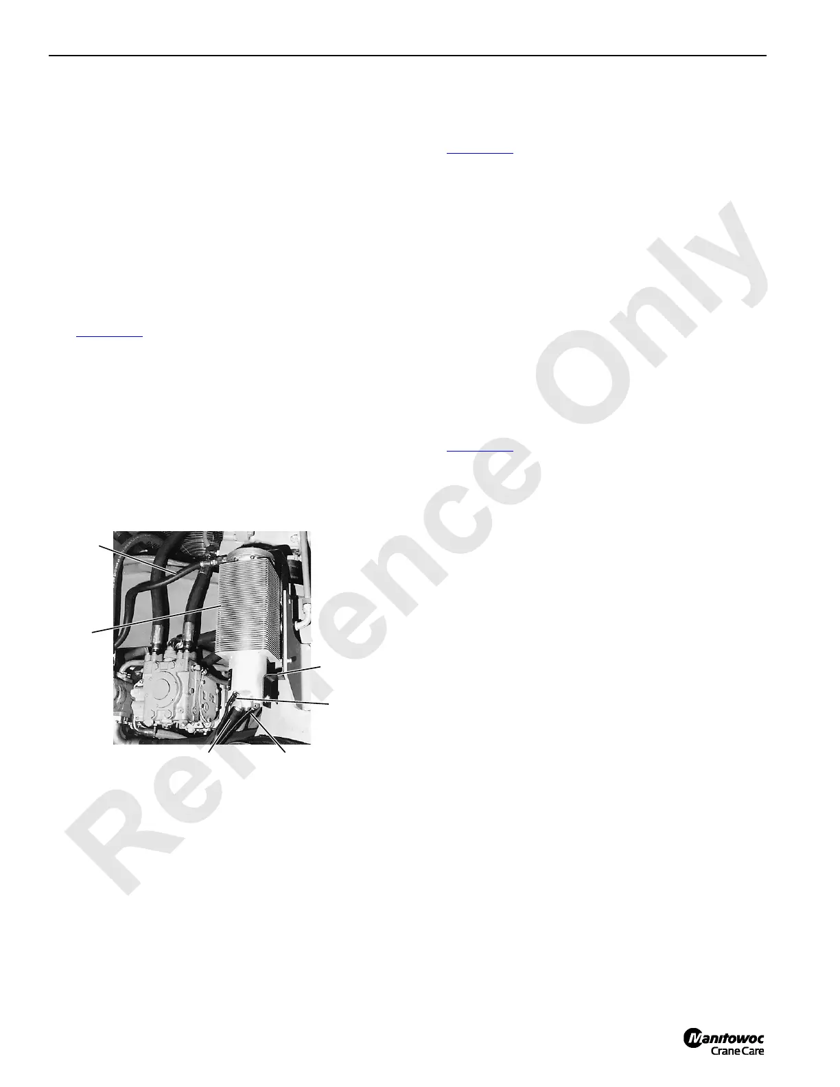
FIGURE 2-35
P777
Air Dryer Installation
(Left Side of Rotating Bed)
From Moisture
Ejector
Mounting
Bracket
From Air
Compressor
Heater
Wires
Air
Dryer
To A i r
Tan ks

 Loading...


