HYDRAULIC AND AIR SYSTEMS 2250 SERVICE/MAINTENANCE MANUAL
2-46
Published 11-06-15, Control # 040-13
N-1 PRESSURE REDUCING VALVE
MAINTENANCE
Operation
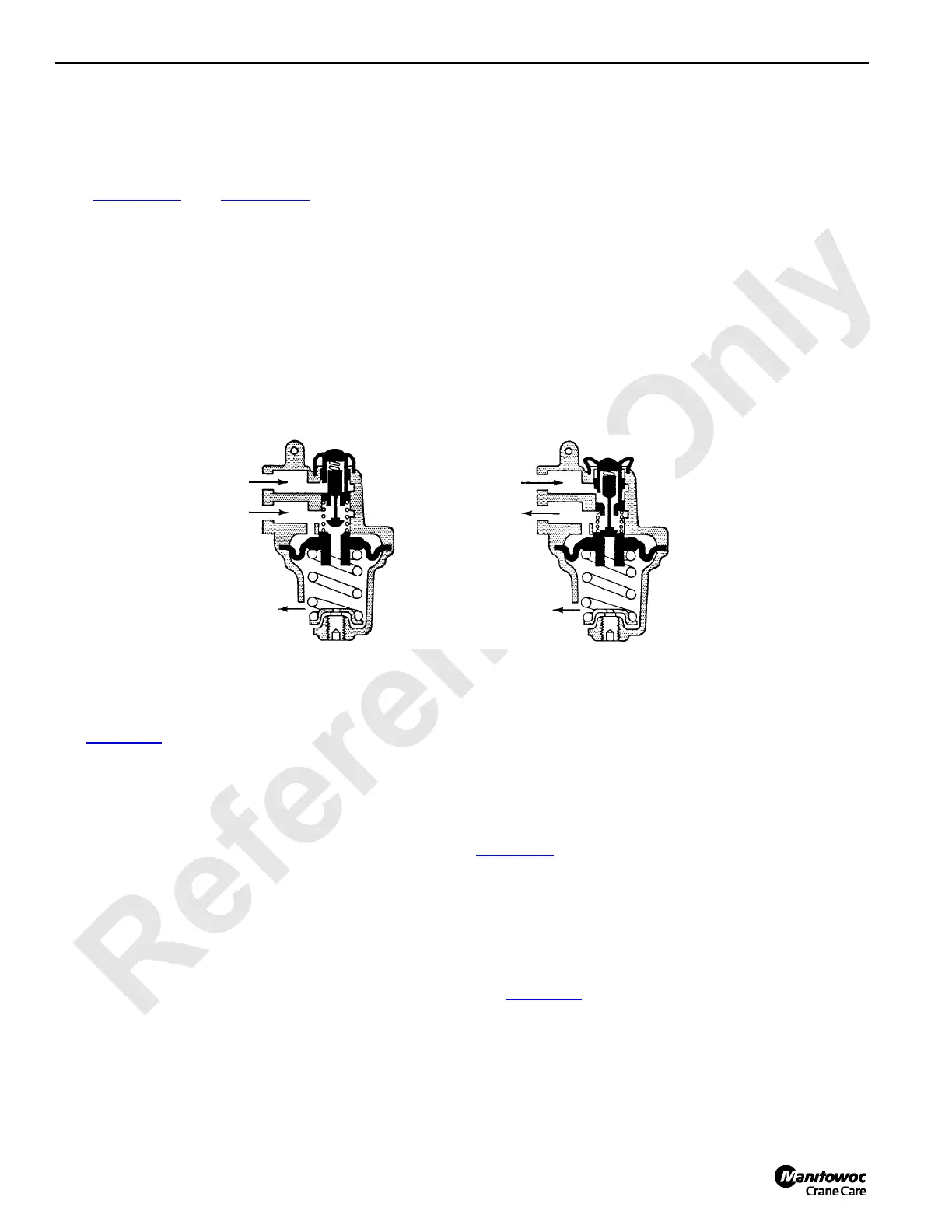
See Figure 2-46 and Figure 2-47 for the following
procedures.
Air pressure from the main supply passes from the in port to
the out port through the unseated inlet valve of inlet and
exhaust valve unit (1). The inlet valve is held off of its seat by
control spring (2) which forces diaphragm (3) and seat (4)
upward. While seat is in the upward position, the exhaust
valve is closed and the inlet valve is held open.
Air pressure at the out port also passes through a sensing
port to the top of diaphragm. When the pressure at the out
port reaches the setting of control spring it is compressed
and the valve assembly moves down far enough to close the
inlet valve and keep the exhaust valve closed. As long as air
pressure at the out port and spring force are balanced, the
inlet and exhaust valve will remain closed.
The valve will automatically compensate for downstream
pressure changes keeping the control circuit at the
predetermined or set pressure. Pressure changes may be
caused by line leakage, temperature changes, or load thrust.
If air pressure at the out port increases over that called for by
the spring setting, the diaphragm will deflect downward
moving exhaust valve seat away from the inlet and exhaust
valve unit and vent the excess pressure. If pressure drops
below that called for by the spring setting, control spring
forces diaphragm upward and exhaust valve seat moves the
inlet valve from its seat, opening the in port to the out port to
restore the pressure called for.
Maintenance
See Figure 2-47 for the following procedures.
Maintenance periods should be scheduled in accordance
with frequency of use and working conditions of valve.
One complete valve should be kept in stock for each four
valves in service. During the maintenance period, change
out the complete valve with the “stand-by” unit. This will
reduce production time loss and allow inspection and
replacement of worn parts in a clean location at a more
convenient time.
NOTE: The operating portion of the valve can be removed
without disturbing the pipe connections.
Remove the valve portion by loosening nut (5) and stud (6).
No special tools are required to maintain the valve.
Completely disassemble the valve. Wash all metal parts in
non-flammable solvent and all rubber parts in soap and
water. Rinse each part thoroughly and blow dry with a low-
pressure air jet. Arrange the parts on a clean surface in the
order of the exploded view.
Examine each part carefully. Flex the diaphragm and
packing rings, and if cracked or worn, replace them. Replace
all parts that may not provide satisfactory service until the
next maintenance period.
Reassemble the valve using the exploded view in
Figure 2-47
as a guide. Lubricate each part before it is put
into place. Use No. 107 Lubriplate on all metal to metal
surfaces and No. 55 Pneumatic Grease on all rubber parts.
Equivalent greases to those recommended can be used.
Store the reconditioned valve in a moisture proof bag.
Adjustments
See Figure 2-47 for the following procedures.
Use adjusting screw (7) to adjust the valve. Turning the
adjusting screw in raises the outlet pressure and turning it
out lowers the outlet pressure.
In
Out
Exhaust
In
Out
Exhaust
Decreasing Pressure
Increasing Pressure
S119
FIGURE 2-46

 Loading...


