INTRODUCTION 2250 SERVICE/MAINTENANCE MANUAL
1-98
Published 11-06-15, Control # 040-13
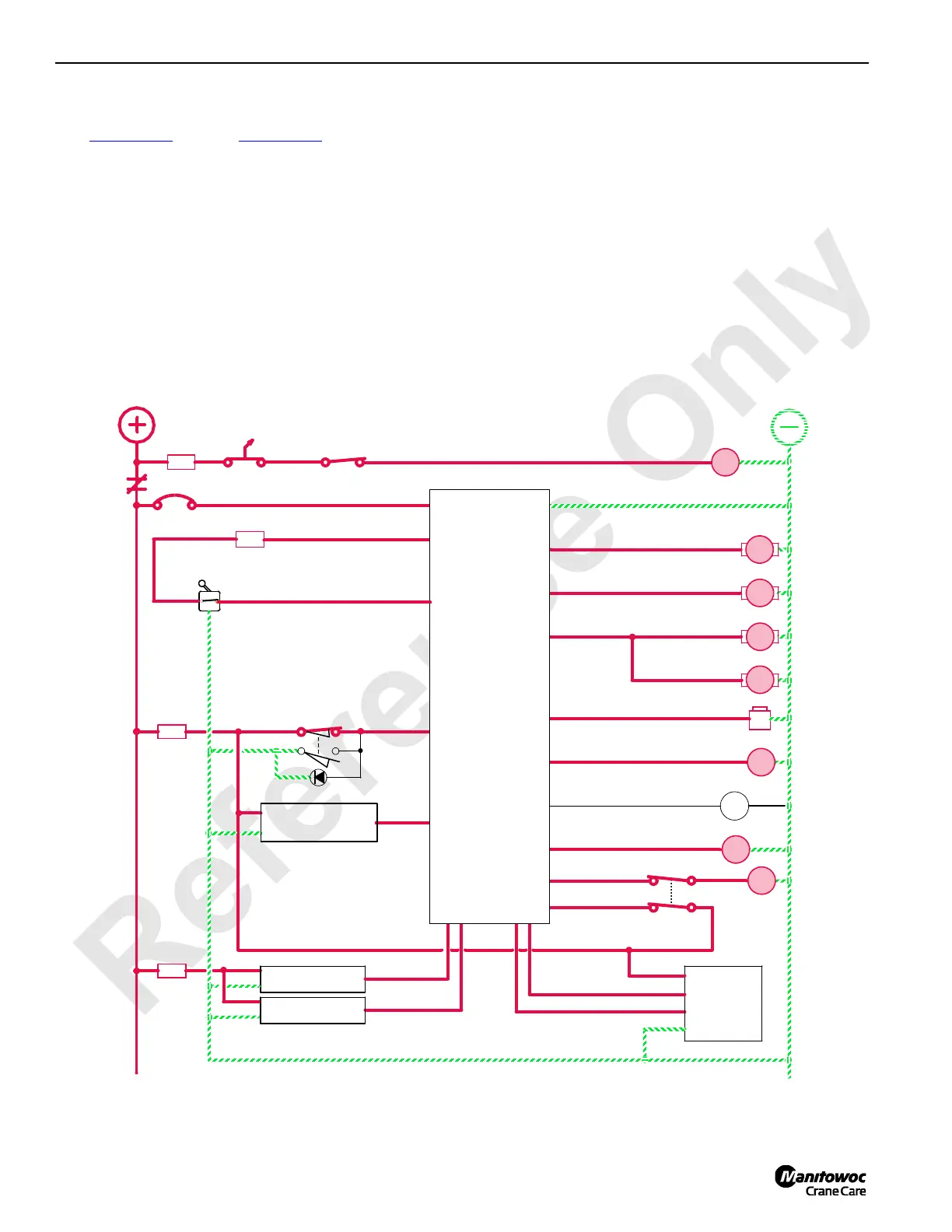
Drum 9 Operation
See Figure 1-62 through Figure 1-65 for the following
procedure.
For MAX-ER configurations drum 9 is mounted in the boom
butt. Source of pressurized hydraulic fluid to operate drum 9
is from the crane crawler travel system or boom hoist system
depending on crane program version.
The left control handle controls drum 9 operation. The
corresponding number 9 green light comes on behind left
control handle. The PC applies drum 9 brakes, controls
crawler travel pump speed, and selects control handle
operation depending on crane mode version. See Operating
Controls topic in Section 3 of MAX-ER Operator Manual for
MAX-ER operation.
Motor loop flushing valves open when system pressure
exceeds 200 psi (14 bar). The sequence/flow control valve
removes 4 GPM (15 L/min) of hot fluid from system by
dumping the fluid in the motor case where it returns to tank.
When drum 9 is operating, the PC monitors input signals
from crawler travel pressure senders and adjust motor
displacement to maintain equal pressure.
The drum flange mounted speed sender monitors drum
speed and controls drum over speed. The speed sender
sends a signal to the crane PC that enables rotation indicator
in drum control handle. This indicator pulsates with a varying
frequency depending on drum rotational speed.
LEFT HANDLE CONTROL
LEFT TRAVEL
SENDER
RIGHT TRAVEL
SENDER
LOWERRAISE
REGULATED 10V DC OUT
8
5A
OFF
3A
8T
88MC
RM17
DRUM 9
FLANGE
ENCODER
80N
A
B
A
B
DRUM 9 LEFT
MOTOR CONTROL
DRUM 9 RIGHT
MOTOR CONTROL
84A
83A
RIGHT TRAVEL
PUMP CONTROL
LEFT TRAVEL
PUMP CONTROL
A
B
B
A
LEFT
ROTATION INDICATOR
88D
TRAVEL/DRUM 9
DIVERTING VALVE
BRAKE
PAWL IN
PAWL OUT
88C
88CA
88E
88N
83DS
8K
84DS
87FA
80P
5DA
5A
8
CAB POWER
OFF
ON
D
B
A
F
8P1
0
8
K1
50 AMP
0
8
10A
5D
5A
88MB
DRUM 9
MINIMUM
BAIL LIMIT
88MA
ENGINE
RUN/STOP
89GA
HS
56
EDC
EDC
PCP
PCP
HS
54
DRUM 9
AS
21
AS
22
DRUM 9
DRUM 9
K1
CRANE
PROGRAMMABLE
CONTROLLER
FIGURE 1-62
HANDLE
90QM
MAST
ACCUMULATOR
SENDER
 Loading...


