Manitowoc Published 11-06-15, Control # 040-13 1-87
2250 SERVICE/MAINTENANCE MANUAL INTRODUCTION
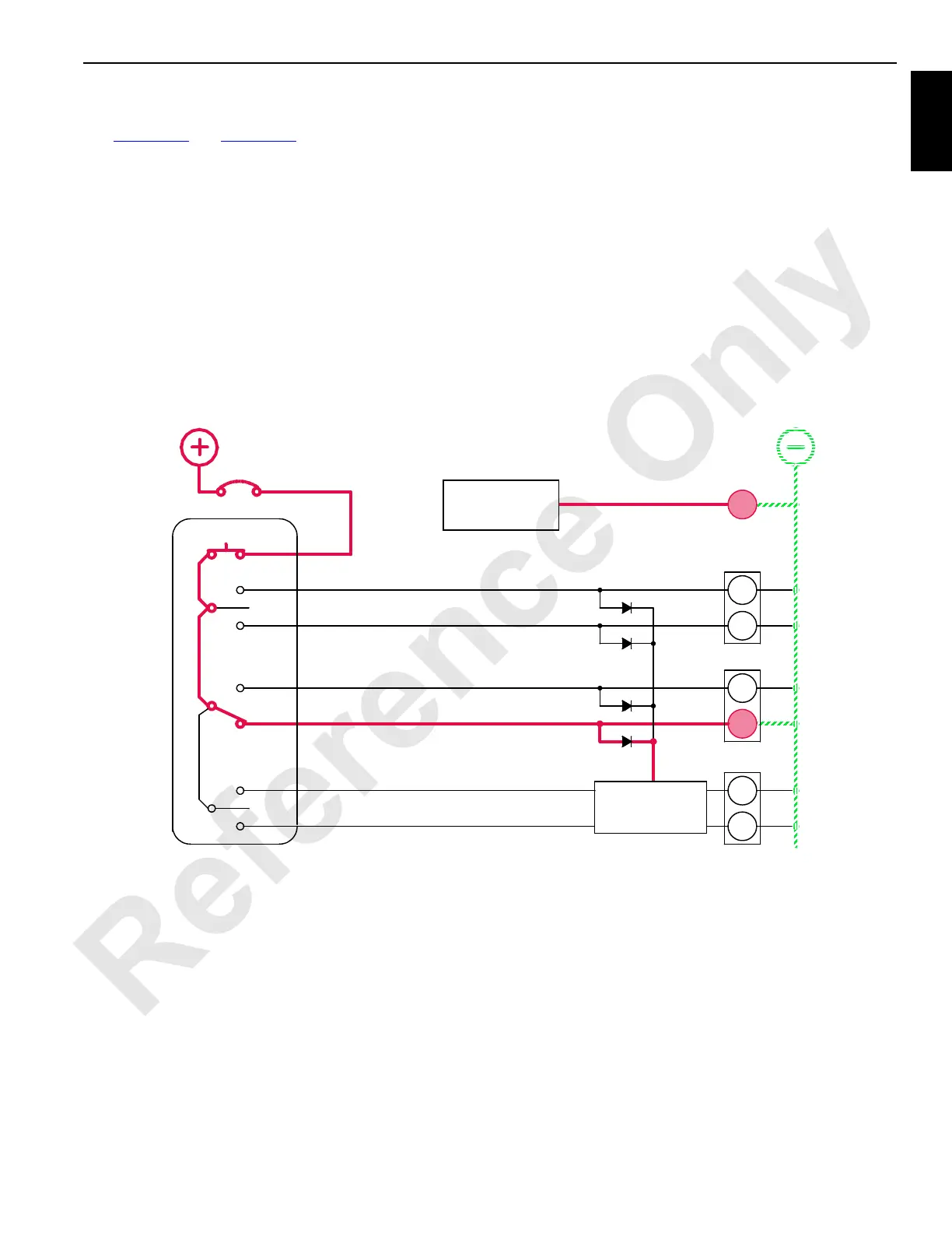
Steering Pin Cylinders
See Figure 1-54 and Figure 1-55 for the following procedure.
Steering pin cylinders disconnect the MAX-ER steering arms
from the counterweight trailer to allow positioning of steering
wheels.
Power is available to MAX-ER remote switch assembly when
power cable (W28) is plugged into receptacle at left side of
counterweight trailer and engine is running. When power
button on MAX-ER remote switch assembly is pressed,
power is enabled to operate steering pins switch. The switch
is spring-returned to OFF position. In off position, the
steering pin cylinders solenoid valve has a closed center with
both cylinder ports blocked.
Steering Pin Cylinders Disengage
When steering pins switch is held in the up disengage
position, an input signal is sent to the PC. A 12-volt output
signal from PC enables the steering pins disengage solenoid
HS-53. Internal pilot supply pressure of 200 psi (14 bar)
enables selected spool to shift the steering pins solenoid
valve. The crane PC sends an output signal to shift crane
auxiliary system disable valve HS-12, to block valve bypass.
Accessory system pressure increases to operate accessory
items. Accessory system fluid enters MAX-ER accessory
valve and flows to rod end of the steering pin cylinders to
disengage pins from right side and left side steering arms.
Return fluid from piston end of cylinder passes through MAX-
ER accessory valve before returning to crane hydraulic tank
through return line. Release steering pins switch to lock
steering pins in position.
Steering Pin Cylinders Engage
When steering pins switch is held in the down engage
position, an input signal is sent to the PC. A 12-volt output
signal from PC enables the steering pins engage solenoid
HS-52. Internal pilot supply pressure of 200 psi (14 bar)
enables selected spool to shift the steering pins solenoid
valve.
The crane PC sends an output signal to shift crane auxiliary
system disable valve HS-12, to block valve bypass.
Accessory system pressure increases to operate accessory
items. Accessory system fluid enters MAX-ER accessory
valve and flows piston end of the steering pins to engage
pins at right side and left side steering arms. Return fluid
from rod end of cylinder passes through MAX-ER accessory
valve before returning to crane hydraulic tank through return
line. Release steering pins switch to lock steering arms in
position.
RM-09
56MB
56MA
8K
90L
90K
POWER
42
43
52
53
41
HS
40
CB
8K
89J4
89K4
0
15 AMP
5A
12
HS
HS
HS
HS
HS
HS
MAX-ER 2000 REMOTE
FIGURE 1-54
89H4
MAX-ER 2000
PROGRAMMABLE
CONTROLLER
AUXILIARY SYSTEM
DISABLE VALVE
CRANE
PROGRAMMABLE
CONTROLLER
88S
SWING/CRAB (STEERING CYLINDER EXTEND
STEERING PINS EXTEND
STEERING PINS RETRACT
COUNTERWEIGHT STRAP
CYLINDER EXTEND
COUNTERWEIGHT STRAP
CYLINDER RETRACT
SWING/CRAB (STEERING CYLINDER RETRACT

 Loading...


