TROUBLESHOOTING 2250 SERVICE/MAINTENANCE MANUAL
10-60
Published 11-06-15, Control # 040-13
Test 25 — Checking and Adjusting Auxiliary System Working Pressure
To determine if piston actuation problems are related to
auxiliary system low-pressure, check the pressure at
auxiliary system disable valve at the upper valve assembly.
To check auxiliary system working pressure:
• Engine must be off and power off, with all brakes and
locks engaged.
• Remove the cap from diagnostic gauge coupler at
disable valve.
• Connect a 0 – 6,000 psi (0 – 413 bar) gauge to
diagnostic gauge coupler.
• Start the engine and retract any hydraulic cylinder
directly driven off upper valve assembly.
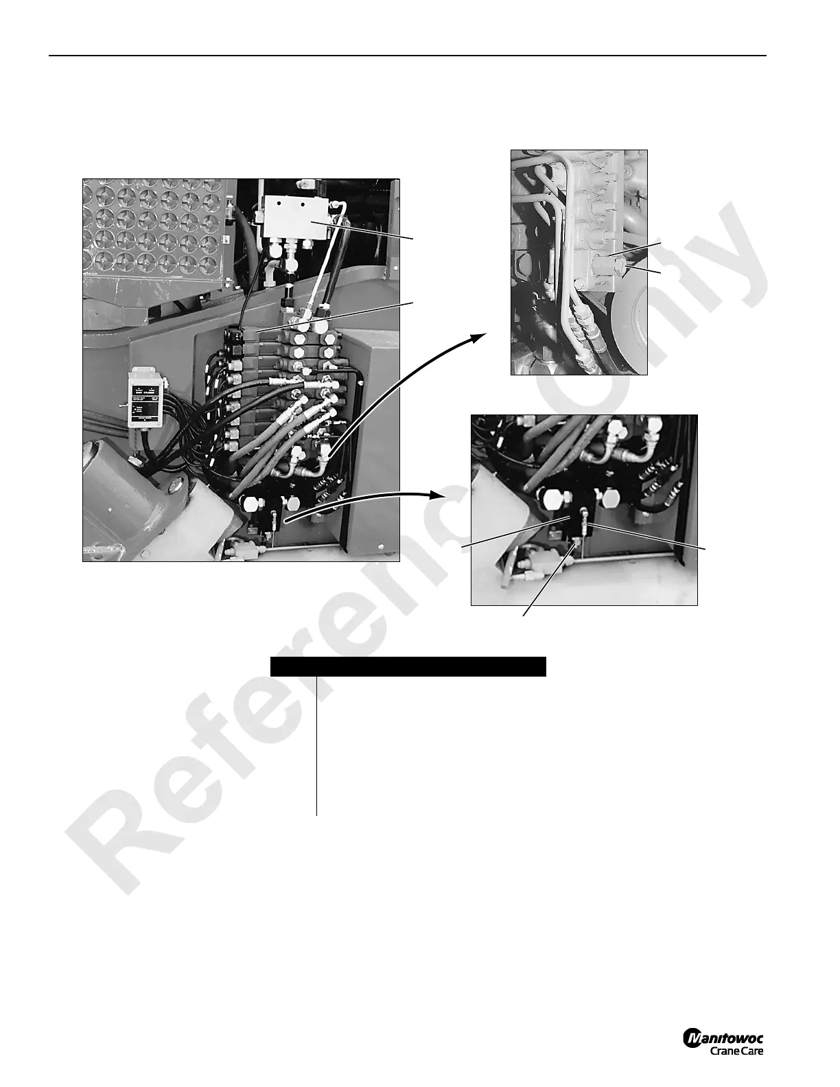
Item Description
1 Proportional flow control valve
2 Upper accessory valve assembly
3 Auxiliary system disable valve
4 Disable valve adjusting screw
5 Disable valve gauge port
6 Accessory relief valve
7 Relief valve adjusting screw

 Loading...


