HYDRAULIC AND AIR SYSTEMS 2250 SERVICE/MAINTENANCE MANUAL
2-20
Published 11-06-15, Control # 040-13
Operating Pressure Checks
It will be necessary to monitor pressure and pump command
on the diagnostic screens of the digital display during the
following procedures. Do not confuse pump command with
handle command on the display.
Boom Hoist Down
1. Stop the engine.
2. Loosen lock nut on adjusting screw at down
multifunction valve in boom hoist pump.
3. Turn adjusting screw out until it stops. Then turn
adjusting screw in 1-3/4 turns.
4. Start and run engine at 1,500 RPM and operate boom
hoist in down direction (no wire rope or load on drums)
Drum should turn freely. If not, proceed as follows:
a. Stop boom hoist drum.
b. Turn down adjusting screw in 1/4 turn.
c. Repeat steps 4
through 4b until drum turns freely.
5. Hold adjusting screw and securely tighten lock nut.
Boom Hoist Up
1. Stop the engine.
2. Disconnect electric plug from boom hoist brake solenoid
valve (Figure 2-24
). This will stall boom hoist pump.
NOTE: If equipped with a luffing hoist, disconnect electric
plug from luffing hoist brake solenoid valve also
(Figure 2-25
).
3. Start and run the engine at 1,500 RPM.
4. Scroll to Drum 4 (boom hoist) diagnostic screen. Monitor
pump pressure and pump command while moving
control handle.
5. Slowly pull boom hoist control handle back. Diagnostic
screen should indicate 5,500 to 6,500 psi (379 to 448
bar) system pressure before 50% pump command is
reached and boom hoist brake (luffing hoist also if
equipped) must not slip.
6. If specified pressure is not indicated or brake(s) slips,
determine cause and correct.
7. Connect electric plug to boom hoist (and luffing hoist if
equipped) brake solenoid valve (Figure 2-24
and
Figure 2-25
).
Swing
1. Stop the engine.
2. Disconnect electric plug from swing brake solenoid
valve (Figure 2-25
). This will stall swing pump.
3. Start and run the engine at 1,500 RPM.
4. Scroll to SWING diagnostic screen. Monitor pump
pressure and command while moving control handle.
5. Slowly move swing control handle in both directions, one
at a time, to check swing pressure.
6. Swing pressure in both directions should be 5,500 to
6,500 psi (379 to 448 bar) before 50% pump command
is reached, and brake must not slip.
7. If specified pressure is not indicated in either direction or
brake slips, determine cause and correct.
8. Connect electric plug to swing brake solenoid valve
(Figure 2-25
).
CAUTION
Overheating Damage!
Do not stall hydraulic system longer than 10 seconds
during following pressure checks or components may be
damaged from overheating.
FIGURE 2-24
Electric
Plug
P924
Boom Hoist Brake Solenoid valve
Access at Left Rear Inboard Side of Rotating Bed
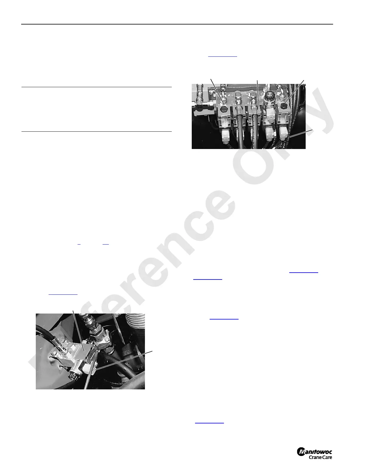
FIGURE 2-25
Access Through Center Hole in Rotating Bed
P973
Electric
Plug
(typical)
Swing Brake
Solenoid Valve
Travel Brake
Solenoid Valve
Luffing Hoist Brake
Solenoid Valve

 Loading...


