Manitowoc Published 11-06-15, Control # 040-13 1-99
2250 SERVICE/MAINTENANCE MANUAL INTRODUCTION
Drum 9 Brake
Drum 9 motors have hydraulic disc brakes that are spring-
applied and hydraulically released. The brakes start to
release at 188 psi (13 bar) and are fully released at 246 psi
(17 bar). The PC controls drum 9 disc brake release solenoid
HS-56 with movement of left control handle, when Drum 9
brake switch is in OFF position. Drum 9 pawl is released and
applied with Drum 9 brake switch.
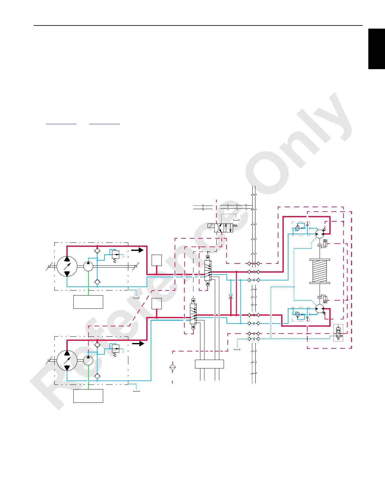
Drum 9 Hoisting (MAX-ER Mode)
See Figure 1-62 and Figure 1-63 for the following procedure.
When left control handle (drum 9) is moved back to raise,
handle neutral switch closes, sending an output voltage of 5
volts or more to the crane PC. The PC sends an output
signal to shift diversion solenoid valve HS-54 to allow fluid
flow from crawler travel pumps through diverting valve to
drum 9 motors.
The crane PC also sends a negative output signal to stroke
each crawler travel pump EDC in the raise direction and a
positive output signal to each motor PCP. The crane PC
checks that block-up limit switches are closed with no other
systems operating limits present.
The PC compares drum-holding pressure to value stored in
pressure memory. When system pressure is high enough,
the PC sends a positive output signal to enable brake
solenoid HS-56. Brake solenoid shifts to block tank port and
opens port to system charge pressure to release brake.
The crane PC sends a negative output voltage to each pump
EDC that tilts swashplate to stroke each pump in raise
direction. Hydraulic fluid at system pressure up to 5,900 psi
(407 bar) flows from pump ports A to port A of motors. Fluid
from motor ports B returns to pump ports B.
350 psi
(24 bar)
RIGHT TRAVEL PUMP
LEFT TRAVEL PUMP
SERVO LINE
TO TRAVEL
MOTORS
BRAKE LINE
FROM
FAN CIRCUIT
T
T
HS54
RM-18
A
B
A
B
HS56
CRANE
DRUM 9
350 psi
(24 bar)
SWIVEL
SUCTION
MANIFOLD
SUCTION
MANIFOLD
FROM BOOM
HOIST CHARGE PUMP
A
B
B
A
BOOM
UP
DOWN
DOWN
UP
FLOW
FLOW
FIGURE 1-63
 Loading...


