Manitowoc Published 11-06-15, Control # 040-13 4-5
2250 SERVICE/MAINTENANCE MANUAL BOOM
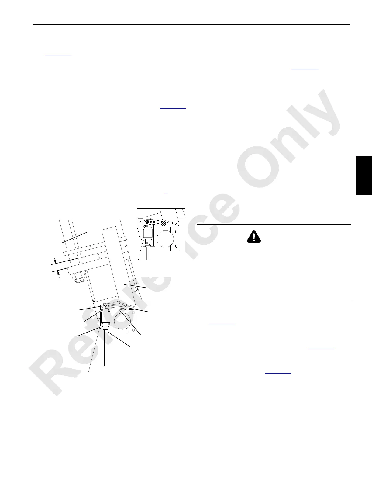
SETUP BOOM ANGLE
See Figure 4-4 for the following procedure.
Perform the following steps when the crane is in the setup
mode and rigged only with the boom butt.
1. Loosen setscrew in limit switch lever so lever is free to
rotate on shaft.
2. Raise boom butt until physical boom stops are 1 in (25,4
mm) from bottoming out as shown in Figure 4-4
(approximately 89° boom angle).
3. Hold roller on lever against actuator. The length of the
lever can be adjusted if a current production limit switch.
4. Turn limit switch shaft CLOCKWISE (viewing switch)
until switch clicks open and hold.
5. Securely tighten setscrew in lever.
6. Lower boom butt several degrees.
7. Slowly raise boom butt.
8. Boom butt must stop at point specified in step 2
. If not,
repeat Setup Boom Angle Adjustment steps.
PHYSICAL BOOM STOP
General
The physical boom stop assembly (Figure 4-5) serves the
following functions:
• Assist in stopping the boom smoothly at any angle
above 80
°.
• Assist in preventing the boom rigging from pulling the
boom back when traveling or setting loads with the
boom at any angle above 80
°.
• Assist in moving the boom forward when lowering the
boom from any angle above 80
°.
• Provide a physical stop at 90
°.
The strut cylinders between the boom stop tubes and the
boom butt have two positions:
• WORKING POSITION (struts fully extended) — The
physical boom stop must be in this position for all crane
operations.
• SHIPPING POSITION (struts fully retracted) — This
position provides maximum clearance for shipping the
boom butt with the physical boom stop installed.
Operation
See Figure 4-5 for the following procedure.
1. Air system pressure of 125 to 137 psi (8,6 to 9,4 bar) is
trapped in boom stop cylinders by a check valve
connected to each cylinder’s inlet port (Figure 4-5
, View
A).
2. When boom is raised to 80
°, boom stop rod ends contact
pins in adapter frame (Figure 4-5
, View B).
3. Cylinder rods then start to compress air trapped in boom
stop cylinders by check valves.
4. As boom is raised higher, pressure of trapped air
increases to exert greater force against boom.
5. If for any reason boom is raised to 90
°, boom stop
cylinders will fully compress air and bottom out to
provide a physical stop.
FIGURE 4-4
A513
Left Side
Physical
Boom Stop
Actuator
Roller
Lever
NOTE: Standard mounting shown. Mounting is raised
approximately 2 ft (0,61 m) when equipped with fold-
under luffing jib.
To A i r Va lv e
Junction Box
Connect electric wires to
normally closed contacts
(1 and 2) inside limit
switch
Past Production
Setup Limit Switch
Setscrew
Shaft
1 in
(25,4 mm)
NOTE: Past Production limit switch has fixed arm.
Current Production limit switch has adjustable arm.
Current Production
Adj. Limit Switch
192115_3
WARNING
Boom Hazard!
Physical boom stop must be installed for all crane
operations.
Physical boom stop does not automatically stop boom at
maximum operating angle. Automatic boom stop must be
installed and properly adjusted (see Automatic Boom Stop
topic in this section).
 Loading...


